Section 1 - FAMILIARIZATION
FUEL
FILLER
CAP
| VENT | STEERING |
|
| |
TRANSMISSION SHIFT LEVER |
| WHEEL |
FUEL TANK |
| OPERATOR’S |
|
| |
REAR BUMPER |
| SEAT |
|
| |
|
| DECK LIFT LEVER |
|
| CONTROL PANEL |
|
| (SEE INSERT) |
|
| CLUTCH/BRAKE |
|
| PEDAL |
DISCHARGE |
|
|
DEFLECTOR |
|
|
CONTROL PANEL
IGNITION | BLADE |
| |
SWITCH |
| ||
PEDALS |
| ||
|
| ||
ENGINE SPEED | BLADE | REMOTE CHOKE | |
LOCATED ON LEFT | |||
CONTROL | LEVER | ||
SIDE OF SEAT | |||
|
| ||
PARK | MOWER |
| |
BRAKE |
| ||
DECK |
| ||
LEVER |
| ||
|
| ||
| MOWER |
| |
| BELT |
| |
| COVER |
|
FIGURE 1.1
1.1 INTRODUCTION
This manual has been prepared for the operator’s of the SNAPPER Rear Engine Rider. Its purpose, aside from recommending standard operating procedures and routine service requirements, is to promote SAFETY through the use of accepted operating practices. Read, Understand and Follow the IMPORTANT SAFETY INSTRUCTIONS on Pages 2 & 3 of this manual and All SAFETY messages on the Rear Engine Rider and its attachments before operating.
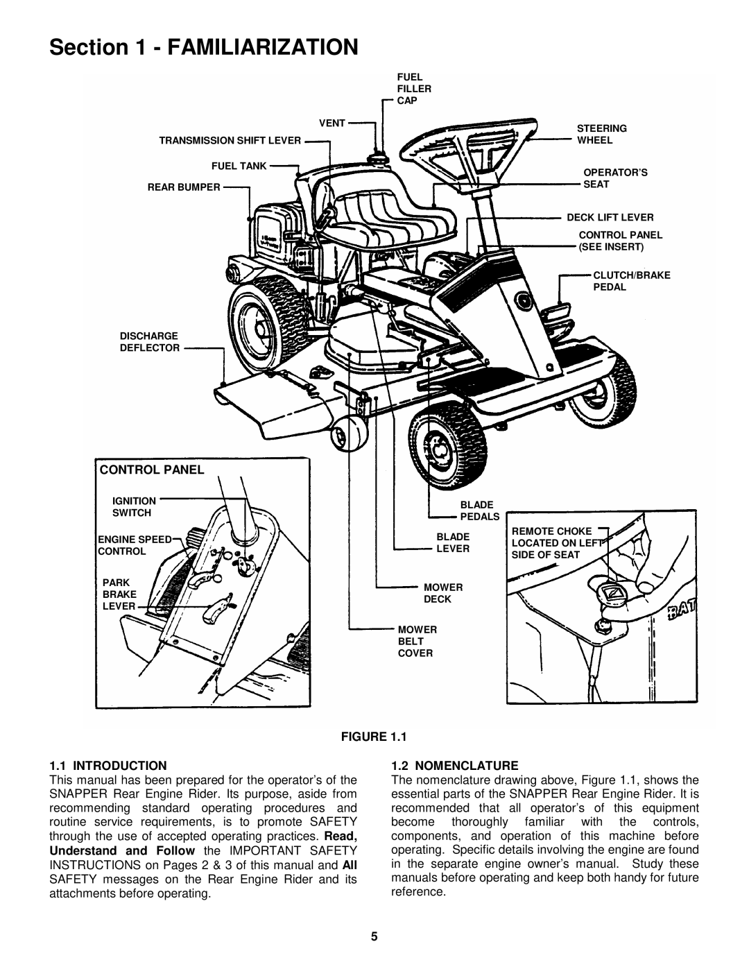
1.2 NOMENCLATURE
The nomenclature drawing above, Figure 1.1, shows the essential parts of the SNAPPER Rear Engine Rider. It is recommended that all operator’s of this equipment become thoroughly familiar with the controls, components, and operation of this machine before operating. Specific details involving the engine are found in the separate engine owner’s manual. Study these manuals before operating and keep both handy for future reference.
5