Installation | DIP Switch Configuration Chart |
|
|
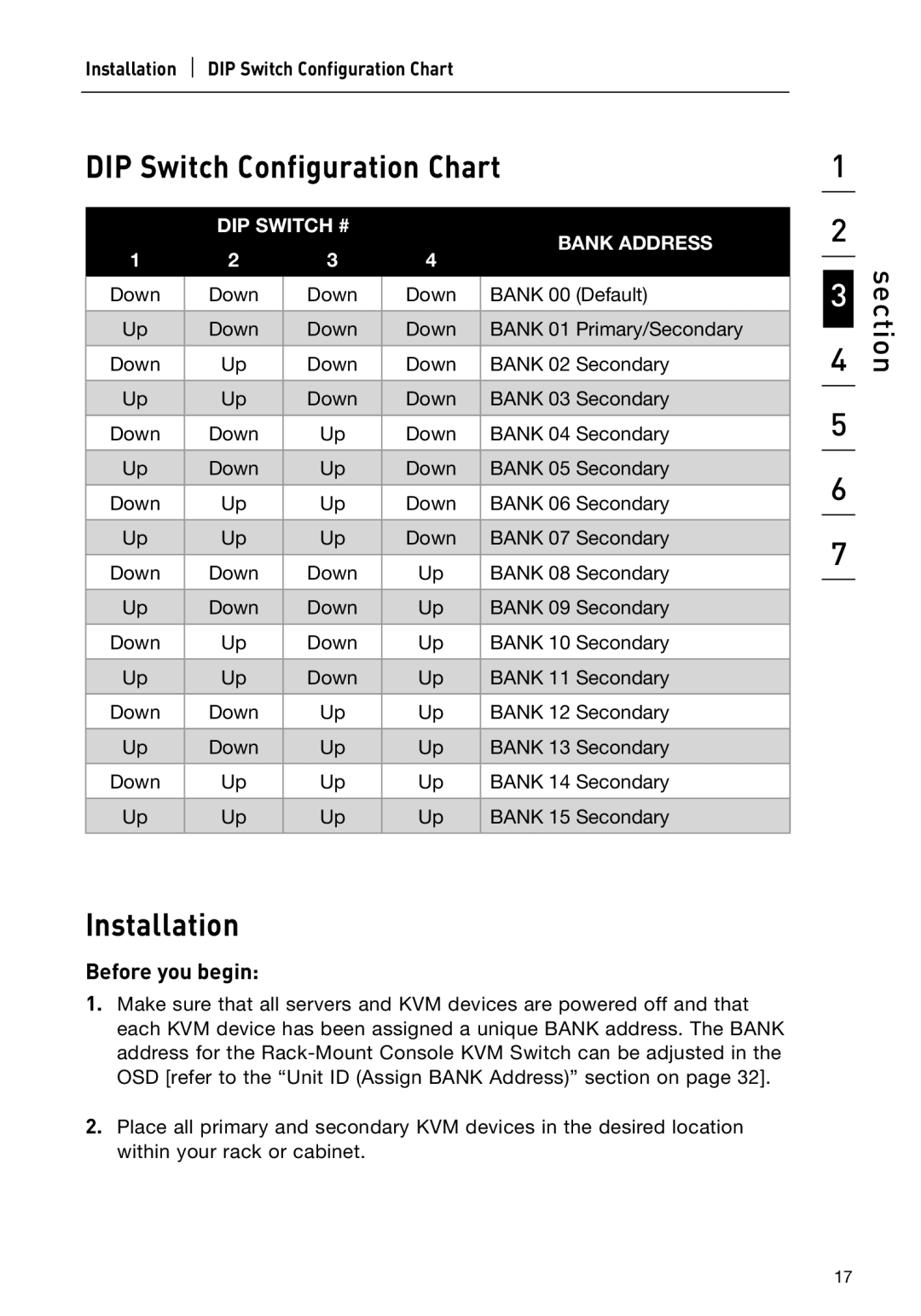
DIP Switch Configuration Chart
|
|
| DIP SWITCH # |
|
|
| BANK ADDRESS | |||
1 | 2 | 3 | 4 |
| ||||||
|
|
| ||||||||
| Down |
| Down |
| Down |
| Down |
| BANK 00 (Default) |
|
|
|
|
|
|
| |||||
|
|
|
|
|
|
|
|
|
|
|
| Up |
| Down |
| Down |
| Down |
| BANK 01 Primary/Secondary |
|
|
|
|
|
|
|
|
|
|
|
|
| Down |
| Up |
| Down |
| Down |
| BANK 02 Secondary |
|
|
|
|
|
|
|
|
|
|
|
|
| Up |
| Up |
| Down |
| Down |
| BANK 03 Secondary |
|
|
|
|
|
|
|
|
|
|
|
|
| Down |
| Down |
| Up |
| Down |
| BANK 04 Secondary |
|
|
|
|
|
|
|
|
|
|
|
|
| Up |
| Down |
| Up |
| Down |
| BANK 05 Secondary |
|
|
|
|
|
|
|
|
|
|
|
|
| Down |
| Up |
| Up |
| Down |
| BANK 06 Secondary |
|
|
|
|
|
|
|
|
|
|
|
|
| Up |
| Up |
| Up |
| Down |
| BANK 07 Secondary |
|
|
|
|
|
|
|
|
|
|
|
|
| Down |
| Down |
| Down |
| Up |
| BANK 08 Secondary |
|
|
|
|
|
|
|
|
|
|
|
|
| Up |
| Down |
| Down |
| Up |
| BANK 09 Secondary |
|
|
|
|
|
|
|
|
|
|
|
|
| Down |
| Up |
| Down |
| Up |
| BANK 10 Secondary |
|
|
|
|
|
|
|
|
|
|
|
|
| Up |
| Up |
| Down |
| Up |
| BANK 11 Secondary |
|
|
|
|
|
|
|
|
|
|
|
|
| Down |
| Down |
| Up |
| Up |
| BANK 12 Secondary |
|
|
|
|
|
|
|
|
|
|
|
|
| Up |
| Down |
| Up |
| Up |
| BANK 13 Secondary |
|
|
|
|
|
|
|
|
|
|
|
|
| Down |
| Up |
| Up |
| Up |
| BANK 14 Secondary |
|
|
|
|
|
|
|
|
|
|
|
|
| Up |
| Up |
| Up |
| Up |
| BANK 15 Secondary |
|
|
|
|
|
|
|
|
|
|
|
|
Installation
Before you begin:
1.Make sure that all servers and KVM devices are powered off and that each KVM device has been assigned a unique BANK address. The BANK address for the
2.Place all primary and secondary KVM devices in the desired location within your rack or cabinet.
1
2
3
4
5
6
7
section
17
