Installation | Connecting the Daisy-Chain Cable |
| |
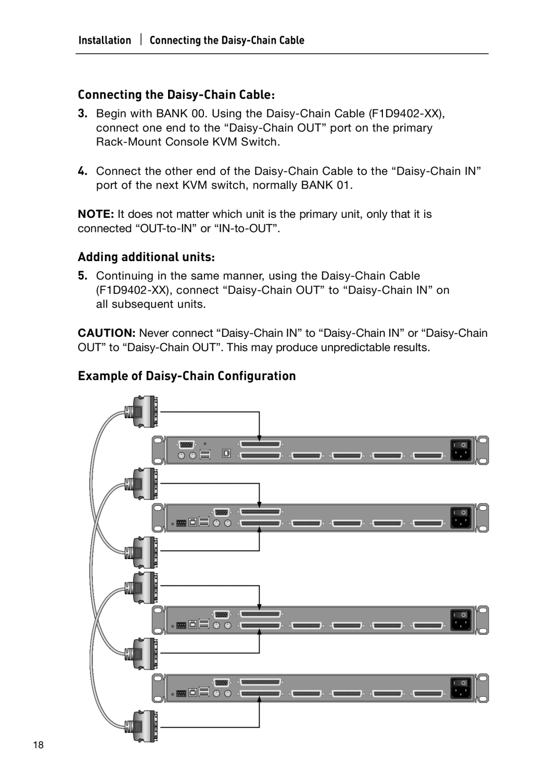
Connecting the Daisy-Chain Cable:
3.Begin with BANK 00. Using the Daisy-Chain Cable (F1D9402-XX), connect one end to the “Daisy-Chain OUT” port on the primary Rack-Mount Console KVM Switch.
4.Connect the other end of the Daisy-Chain Cable to the “Daisy-Chain IN” port of the next KVM switch, normally BANK 01.
NOTE: It does not matter which unit is the primary unit, only that it is connected “OUT-to-IN” or “IN-to-OUT”.
Adding additional units:
5.Continuing in the same manner, using the Daisy-Chain Cable (F1D9402-XX), connect “Daisy-Chain OUT” to “Daisy-Chain IN” on all subsequent units.
CAUTION: Never connect “Daisy-Chain IN” to “Daisy-Chain IN” or “Daisy-Chain OUT” to “Daisy-Chain OUT”. This may produce unpredictable results.
Example of Daisy-Chain Configuration