STEP 6
INSTALL OPERATOR PROTECTIVE STRUCTURE (OPS)
The installation of the Operator Protective Structure requires two people. The mounting hardware for the OPS and seat belts must be properly torqued. Do Not modify the OPS in any way. Install the OPS with the “WARNING” sign on the right (passenger’s) side of the machine.
STEP 7
ENGINE OIL AND TRANSMISSION FLUID
The engine oil and transmission fluid must be checked before operation.
1.Fill engine crankcase to proper level. Refer to Engine Owner’s Manual for capacity and oil specifications. Check with dipstick unthreaded.
2.Check transmission fluid level. Bring to full level as necessary using MOBILFLUID 424 or equivalent. Check with dipstick fully threaded.
HEAT
SHIELD
STEP 8
ACTIVATE BATTERY
Battery is located under the operator’s seat. Remove battery from compartment before activating or charging. Activate and charge the battery in well ventilated area away from sparks and flame. Do Not smoke.
1.Remove battery from the battery compartment before charging.
2.Place battery in a well ventilated area on a level
FUEL TANK |
|
|
| REMOVE TOP | |
STRAPS |
| |
| TWO BOLTS | |
|
| |
|
|
|
|
|
|
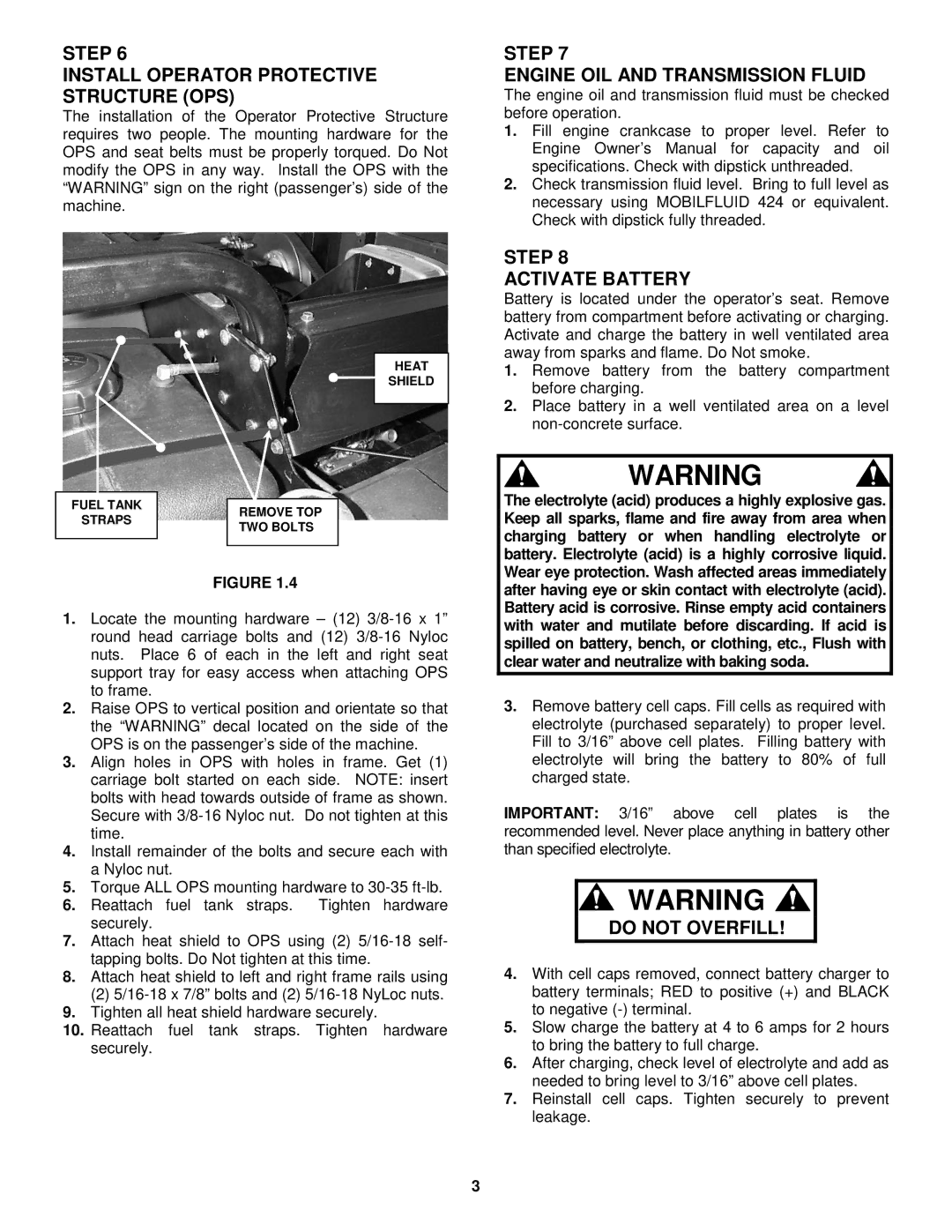
FIGURE 1.4
1.Locate the mounting hardware – (12)
2.Raise OPS to vertical position and orientate so that the “WARNING” decal located on the side of the OPS is on the passenger’s side of the machine.
3.Align holes in OPS with holes in frame. Get (1) carriage bolt started on each side. NOTE: insert bolts with head towards outside of frame as shown. Secure with
4.Install remainder of the bolts and secure each with a Nyloc nut.
5.Torque ALL OPS mounting hardware to
6.Reattach fuel tank straps. Tighten hardware securely.
7.Attach heat shield to OPS using (2)
8.Attach heat shield to left and right frame rails using
(2)
9.Tighten all heat shield hardware securely.
10.Reattach fuel tank straps. Tighten hardware securely.
3
WARNING
The electrolyte (acid) produces a highly explosive gas. Keep all sparks, flame and fire away from area when charging battery or when handling electrolyte or battery. Electrolyte (acid) is a highly corrosive liquid. Wear eye protection. Wash affected areas immediately after having eye or skin contact with electrolyte (acid). Battery acid is corrosive. Rinse empty acid containers with water and mutilate before discarding. If acid is spilled on battery, bench, or clothing, etc., Flush with clear water and neutralize with baking soda.
3.Remove battery cell caps. Fill cells as required with electrolyte (purchased separately) to proper level. Fill to 3/16” above cell plates. Filling battery with electrolyte will bring the battery to 80% of full charged state.
IMPORTANT: 3/16” above cell plates is the recommended level. Never place anything in battery other than specified electrolyte.
![]() WARNING
WARNING ![]()
DO NOT OVERFILL!
4.With cell caps removed, connect battery charger to battery terminals; RED to positive (+) and BLACK to negative
5.Slow charge the battery at 4 to 6 amps for 2 hours to bring the battery to full charge.
6.After charging, check level of electrolyte and add as needed to bring level to 3/16” above cell plates.
7.Reinstall cell caps. Tighten securely to prevent leakage.