Axion / 150Z Series
Setting Up the Ground Speed Control Levers
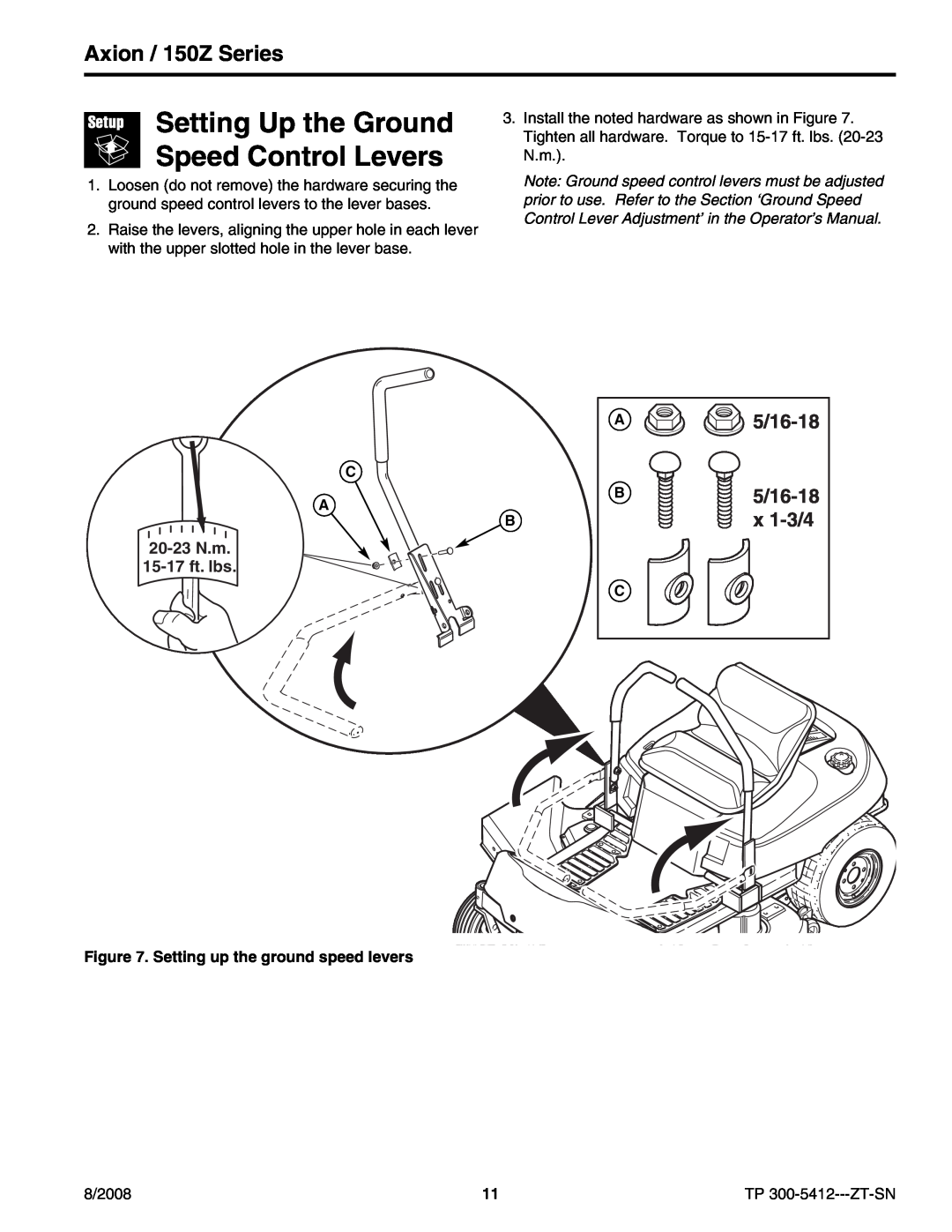
1.Loosen (do not remove) the hardware securing the ground speed control levers to the lever bases.
2.Raise the levers, aligning the upper hole in each lever with the upper slotted hole in the lever base.
3.Install the noted hardware as shown in Figure 7. Tighten all hardware. Torque to
Note: Ground speed control levers must be adjusted prior to use. Refer to the Section ‘Ground Speed Control Lever Adjustment’ in the Operator’s Manual.
C
A
B
20-23 N.m.
A
B
C

5/16-18
Figure 7. Setting up the ground speed levers
8/2008 | 11 | TP |