Section 4 - REPAIR & ADJUSTMENTS
4.1.5. GROUND SPEED ADJUSTMENT
NOTE: It is recommended to remove the drive system cover and check rubber drive engagement with drive disc when adjusting ground speed.
1.Tilt machine forward to gain access to drive system area. Secure machine in the tilted position to prevent tipping over. Remove drive system cover plate. See Figure 4.7.
2.Loosen the top screw that connects the shift rod to the shift hub. See Figure 4.8.
3.Move shift rod clockwise to obtain more ground speed or counter clockwise for less ground speed. Retighten top screw after adjustment. See Figure 4.8.
|
| CLOCKWISE | |
|
|
| |
| COUNTERCLOCKWISE | LOOSEN TOP SCREW |
|
| AND MOVE SHIFT HUB |
| |
|
|
| |
| SHIFT | CLOCKWISE OR |
|
| COUNTERCLOCKWISE TO |
| |
| HUB |
| |
| ADJUST GROUND SPEED |
| |
|
|
| |
|
|
|
|
FIGURE 4.8
4.Check drive system to insure the rubber drive tire has full contact with drive disc. Shift through all speeds and note the position of rubber drive tire on the drive disc. See Figure 4.9.
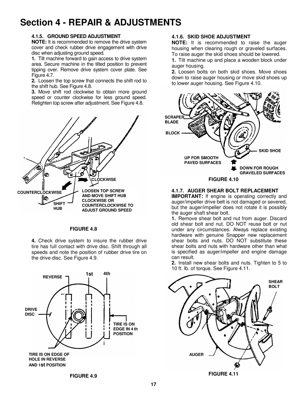
4.1.6. SKID SHOE ADJUSTMENT
NOTE: It is recommended to raise the auger housing when clearing rough or graveled surfaces. To raise auger the skid shoes should be lowered.
1.Tilt machine up and place a wooden block under auger housing.
2.Loosen bolts on both skid shoes. Move shoes down to raise auger housing or move skid shoes up to lower auger housing. See Figure 4.10.
SCRAPER
BLADE
BLOCK
SKID SHOE
UP FOR SMOOTH
PAVED SURFACES
DOWN FOR ROUGH GRAVELED SURFACES
FIGURE 4.10
4.1.7.AUGER SHEAR BOLT REPLACEMENT IMPORTANT: If engine is operating correctly and auger/impeller drive belt is not damaged or severed, but the auger/impeller does not rotate it is possibly the auger shaft shear bolt.
1. Remove shear bolt and nut from auger. Discard old shear bolt and nut. DO NOT reuse bolt or nut under any circumstances. Always replace existing hardware with genuine Snapper new replacement shear bolts and nuts. DO NOT substitute these shear bolts and nuts with hardware other than what is specified as auger/impeller and engine damage can result.
2. Install new shear bolts and nuts. Tighten to 5 to 10 ft. lb. of torque. See Figure 4.11.
REVERSE
DRIVE
DISC
1st 4th
TIRE IS ON
EDGE IN 4 th
POSITION
SHEAR BOLT
TIRE IS ON EDGE OF
HOLE IN REVERSE
AND 1st POSITION
FIGURE 4.9
17
AUGER
FIGURE 4.11