Section 4 - REPAIR & ADJUSTMENTS
WARNING
DO NOT attempt any adjustments, maintenance, service, or repairs, with engine running. Stop auger. Stop engine. Remove key. Disconnect spark plug wire and secure wire away from spark plug. Before tilting machine, drain all the fuel from fuel tank. Allow engine to run, outdoors where fumes can be safely dissipated, until all fuel is removed from carburetor.
4.1.2. AUGER BELT IDLER PULLEY ADJUSTMENT
(Continued From Previous Page)
4.Recheck cable for proper extension (3/8”).
5.Reinstall belt cover.
4.1.3. AUGER BELT REPLACEMENT
Inspect belt frequently for signs of excessive wear. Visually check engine drive belt for cracking, fraying, severed or belt strands exposed.
1.Remove belt cover. Refer to Figure 4.2.
2.Remove discharge chute.
3.Loosen both auger/impeller belt guides. See Figure 4.4.
IMPORTANT: Wheel drive belt will have to be removed from around engine drive pulley and engine shaft to install auger drive belt.
4.Remove auger drive belt from around engine pulley. See Figure 4.4.
AUGER DRIVE BELT
LOOSEN
BELT
WHEEL DRIVE
GUIDE
BELT
LOOSEN
BELT GUIDE
DRIVE DISC
PULLEY
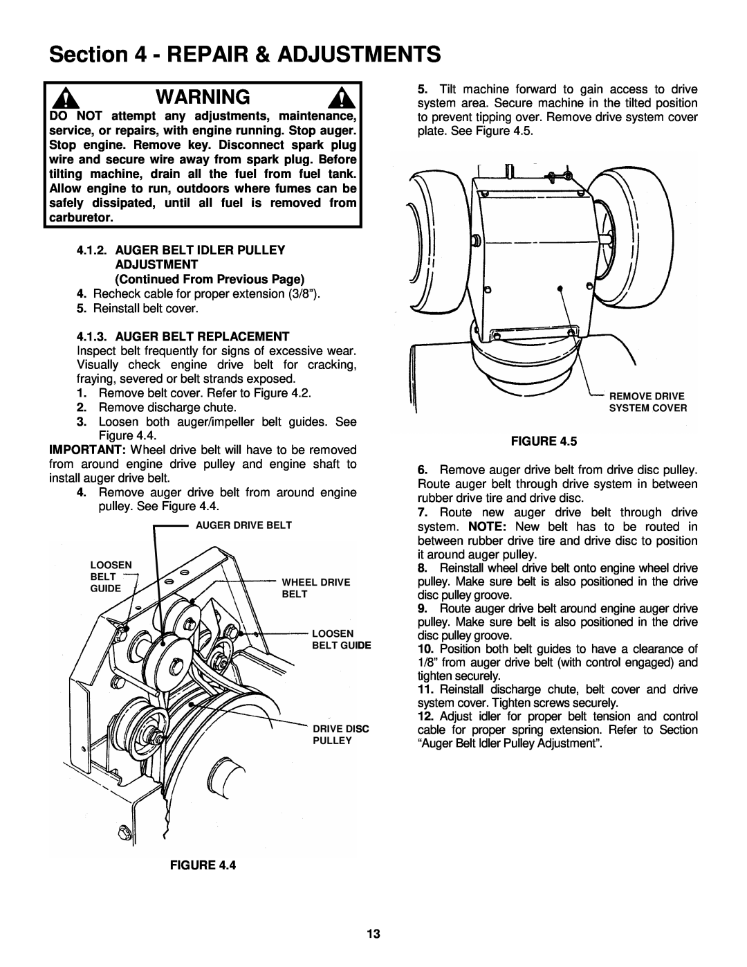
5.Tilt machine forward to gain access to drive system area. Secure machine in the tilted position to prevent tipping over. Remove drive system cover plate. See Figure 4.5.
REMOVE DRIVE
SYSTEM COVER
FIGURE 4.5
6.Remove auger drive belt from drive disc pulley. Route auger belt through drive system in between rubber drive tire and drive disc.
7.Route new auger drive belt through drive system. NOTE: New belt has to be routed in between rubber drive tire and drive disc to position it around auger pulley.
8.Reinstall wheel drive belt onto engine wheel drive pulley. Make sure belt is also positioned in the drive disc pulley groove.
9.Route auger drive belt around engine auger drive pulley. Make sure belt is also positioned in the drive disc pulley groove.
10.Position both belt guides to have a clearance of 1/8” from auger drive belt (with control engaged) and tighten securely.
11.Reinstall discharge chute, belt cover and drive system cover. Tighten screws securely.
12.Adjust idler for proper belt tension and control cable for proper spring extension. Refer to Section “Auger Belt Idler Pulley Adjustment”.
FIGURE 4.4
13