Section 4 - ADJUSTMENT & REPAIR
WARNING
DO NOT attempt any adjustments, maintenance or service with the engine or blades running. STOP blades. STOP engine. Set brake. Remove key. Remove spark plug wire from spark plug and secure wire away from spark plug. Engine and components can be extremely hot. Avoid burns by allowing engine and components sufficient time to cool.
4.1ENGINE ADJUSTMENTS & REPAIR
Refer to the engine owner's manual for those adjustments and/or repairs that can be made by the owner.
4.2MOWER DECK & COMPONENT ADJUSTMENTS The following mower deck and component adjustments and repairs can be made by the owner. However, if there is difficulty in achieving these adjustments and repairs, it is recommended that these repairs be made by an authorized SNAPPER dealer.
WARNING
Blades must stop rotating in 5 seconds or less after blades have been turned off. DO NOT operate machine until blade brake has been repaired and functioning properly. Contact your SNAPPER dealer for assistance.
4.2.1.BLADE BRAKE ADJUSTMENT
The blade brake when functioning properly will stop blade rotation in 5 seconds or less. The brake requires no adjustment. If blades continue to rotate after 5 seconds the blade brake must be repaired. Contact your authorized SNAPPER dealer for assistance.
d.Disconnect rear sector plates and allow center, rear of deck to rest on angle iron.
e.Measure the distance from blade tips to floor. If the measurement is within 1/8” from
REAR TO FRONT VIEW OF DECK
| X | X - 1/8” |
| |
|
|
|
| |
|
|
|
|
|
|
|
|
|
|
ANGLE IRON
FIGURE 4.1
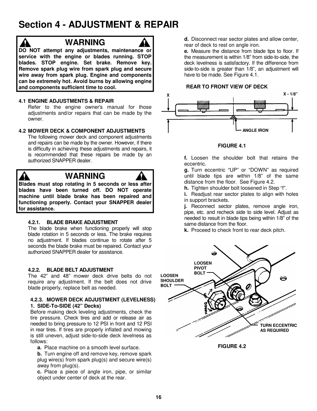
f. Loosen the shoulder bolt that retains the eccentric.
g. Turn eccentric “UP” or “DOWN” as required until blade tips are within 1/8” of the same distance from the floor. See Figure 4.2.
h.Tighten shoulder bolt loosened in Step “f”.
i.Readjust rear sector plates to align with holes in support brackets.
j.Reconnect sector plates, remove angle iron, pipe, etc. and recheck side to side level. Adjust as needed to result in blade tips being within 1/8” of the same distance from the floor.
k.Proceed to check front to rear deck pitch.
4.2.2.BLADE BELT ADJUSTMENT
The 42” and 48” mower deck drive belts do not require any adjustment. If the belt does not drive blade properly, replace belt as needed.
4.2.3.MOWER DECK ADJUSTMENT (LEVELNESS) 1. SIDE-To-SIDE (42” Decks)
Before making deck leveling adjustments, check the tire pressure. Check tires and add or release air as needed to bring pressure to 12 PSI in front and 12 PSI in rear tires. If tires are properly inflated and mowing is still uneven, adjust
a. Place machine on a smooth level surface.
b. Turn engine off and remove key, remove spark plug wire(s) from spark plug(s) and secure wire(s) away from plug(s).
c. Place a piece of angle iron, pipe, or similar object under center of deck at the rear.
LOOSEN SHOULDER BOLT
LOOSEN
PIVOT
BOLT
TURN ECCENTRIC
AS REQUIRED
FIGURE 4.2
16