Section 4 - REPAIR & ADJUSTMENTS
WARNING
DO NOT attempt any maintenance, adjustments or service with engine and blade running. STOP engine and blade. Disconnect spark plug wire and secure away from spark plug. Engine and components are HOT. Avoid serious burns, allow sufficient time for all components to cool.
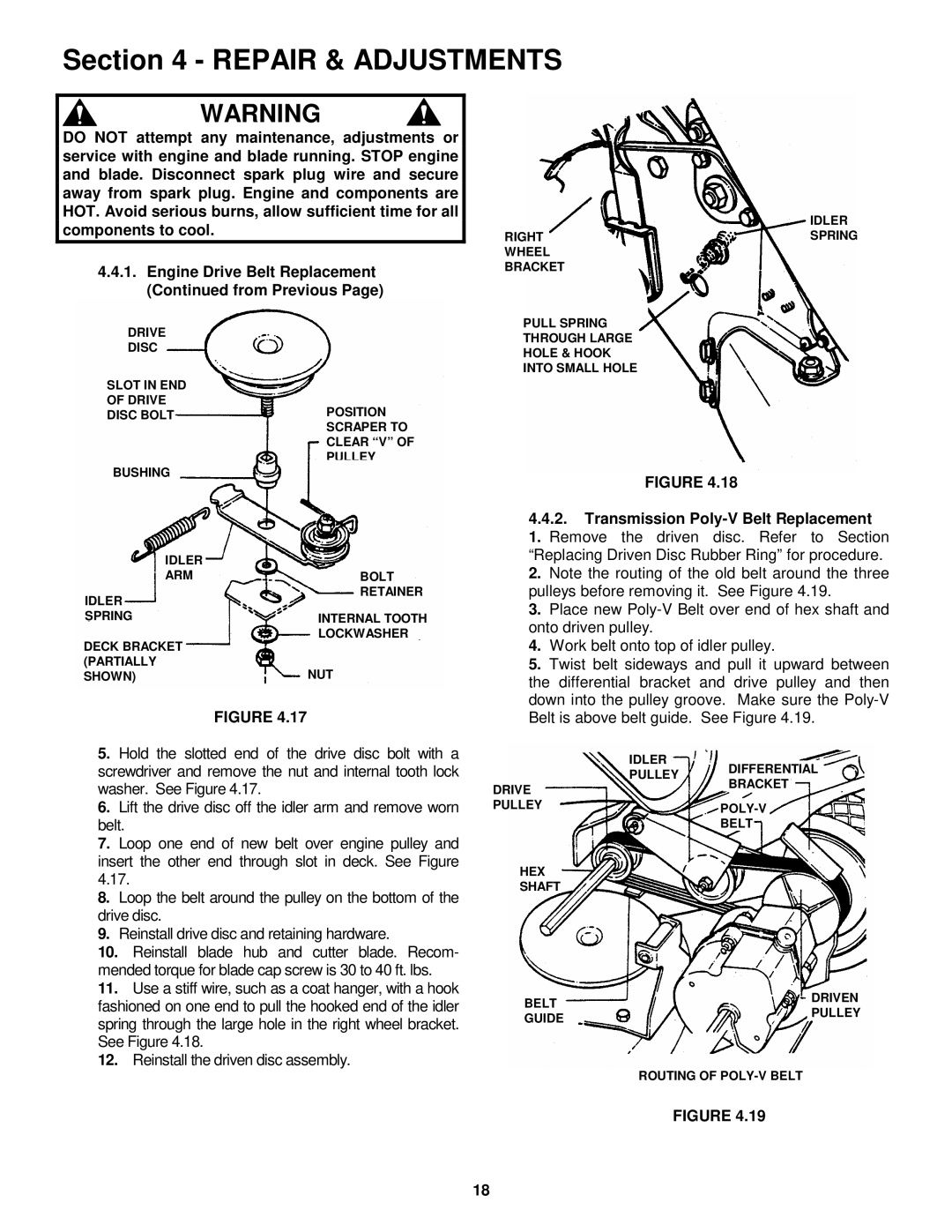
4.4.1.Engine Drive Belt Replacement (Continued from Previous Page)
DRIVE
DISC
SLOT IN END
OF DRIVE
DISC BOLTPOSITION SCRAPER TO
CLEAR “V” OF PULLEY
BUSHING
IDLER |
|
ARM | BOLT |
IDLER | RETAINER |
| |
SPRING | INTERNAL TOOTH |
DECK BRACKET | LOCKWASHER |
| |
(PARTIALLY | NUT |
SHOWN) |
FIGURE 4.17
5.Hold the slotted end of the drive disc bolt with a screwdriver and remove the nut and internal tooth lock washer. See Figure 4.17.
6.Lift the drive disc off the idler arm and remove worn belt.
7.Loop one end of new belt over engine pulley and insert the other end through slot in deck. See Figure
8.Loop the belt around the pulley on the bottom of the drive disc.
9.Reinstall drive disc and retaining hardware.
10.Reinstall blade hub and cutter blade. Recom- mended torque for blade cap screw is 30 to 40 ft. lbs.
11.Use a stiff wire, such as a coat hanger, with a hook fashioned on one end to pull the hooked end of the idler spring through the large hole in the right wheel bracket. See Figure 4.18.
12.Reinstall the driven disc assembly.
IDLER
RIGHTSPRING WHEEL
BRACKET
PULL SPRING
THROUGH LARGE
HOLE & HOOK
INTO SMALL HOLE
FIGURE 4.18
4.4.2.Transmission
3. Place new
4. Work belt onto top of idler pulley.
5. Twist belt sideways and pull it upward between the differential bracket and drive pulley and then down into the pulley groove. Make sure the
IDLER
| PULLEY | DIFFERENTIAL |
| BRACKET | |
DRIVE |
| |
|
| |
PULLEY |
| |
|
| |
|
| BELT |
HEX |
|
|
SHAFT |
|
|
BELT | DRIVEN | |
PULLEY | ||
GUIDE | ||
| ||
| ROUTING OF |
FIGURE 4.19
18