•If the spacer tube has deep grooves worn into it, do not reuse the part - replace it using an exact factory replacement part only.
•Rotate or flip the hammer to provide a new cutting edge, or install a new hammer if worn out or dam- aged.
•Reassemble the hammer and related parts and hardware, observing the correct assembly sequence as shown in figures 19 and 20.
8.Tighten the capscrew securely. For proper assembly, do not exceed 45 ft. lbs. of torque when tightening.
9.Rotate rotor to expose next shredding hammer, and repeat steps 6 - 8. When replacing “J” hammers, observe the correct placement of the blade toward the inside or outside of the rotor assembly.
10.If chipping knives are to be inspected or serviced, go to the following section on chipping knives. If service is to be done on shredding hammers only, proceed to next step below.
11.Reassemble the rotor housing using the
12.Reattach the shredder hopper, repeating the assem- bly sequence used when the unit was first assem- bled.
13.Check all hardware for tightness and correct assem- bly before attempting to start unit. Do not attempt to start unit if extra hardware is left over after reassem- bly is complete. Check all hammer assemblies before proceeding.
Troubleshooting & Repair
*2560
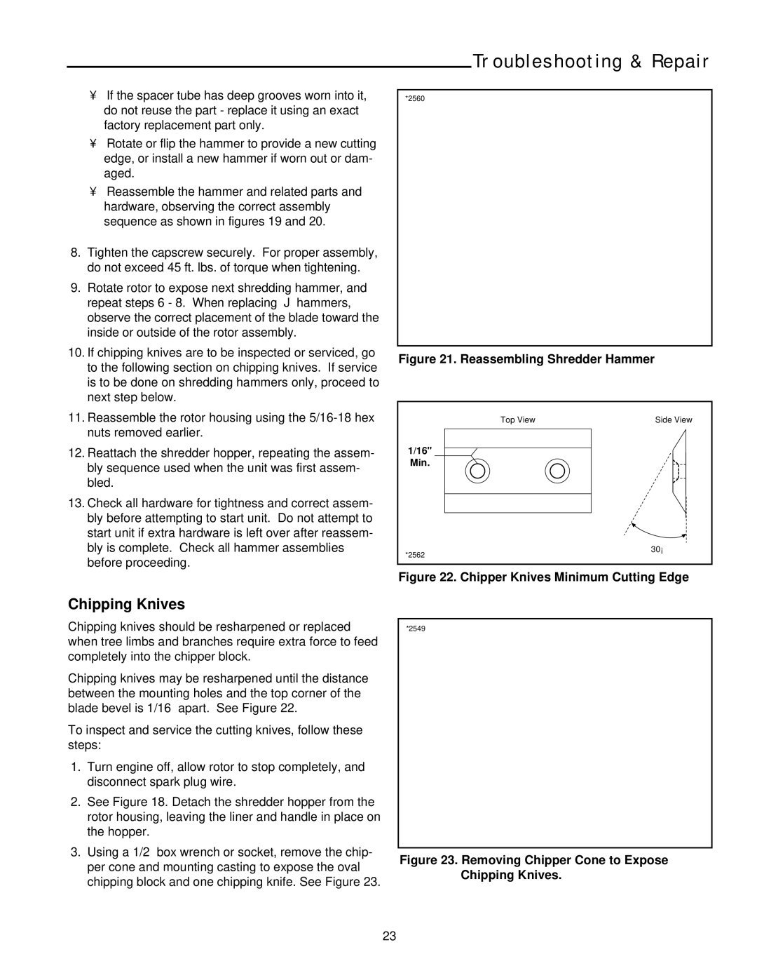
Figure 21. Reassembling Shredder Hammer
Top View | Side View |
1/16"
Min.
30°
*2562
Figure 22. Chipper Knives Minimum Cutting Edge
Chipping Knives
Chipping knives should be resharpened or replaced when tree limbs and branches require extra force to feed completely into the chipper block.
Chipping knives may be resharpened until the distance between the mounting holes and the top corner of the blade bevel is 1/16” apart. See Figure 22.
To inspect and service the cutting knives, follow these steps:
1.Turn engine off, allow rotor to stop completely, and disconnect spark plug wire.
2.See Figure 18. Detach the shredder hopper from the rotor housing, leaving the liner and handle in place on the hopper.
3.Using a 1/2” box wrench or socket, remove the chip- per cone and mounting casting to expose the oval chipping block and one chipping knife. See Figure 23.
*2549
Figure 23. Removing Chipper Cone to Expose Chipping Knives.
23