Operation
DEFLECTOR
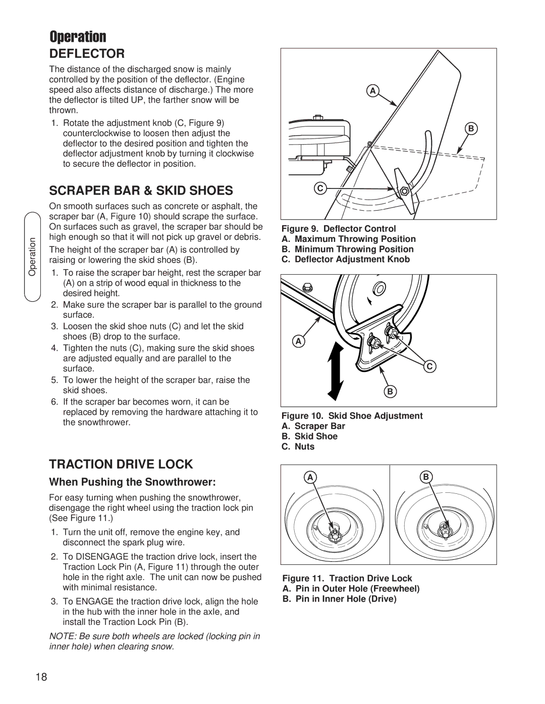
The distance of the discharged snow is mainly controlled by the position of the deflector. (Engine speed also affects distance of discharge.) The more the deflector is tilted UP, the farther snow will be thrown.
1.Rotate the adjustment knob (C, Figure 9) counterclockwise to loosen then adjust the deflector to the desired position and tighten the deflector adjustment knob by turning it clockwise to secure the deflector in position.
| SCRAPER BAR & SKID SHOES | |
| On smooth surfaces such as concrete or asphalt, the | |
| scraper bar (A, Figure 10) should scrape the surface. | |
| On surfaces such as gravel, the scraper bar should be | |
Operation | high enough so that it will not pick up gravel or debris. | |
1. To raise the scraper bar height, rest the scraper bar | ||
| The height of the scraper bar (A) is controlled by | |
| raising or lowering the skid shoes (B). | |
|
| (A) on a strip of wood equal in thickness to the |
|
| desired height. |
| 2. | Make sure the scraper bar is parallel to the ground |
|
| surface. |
| 3. | Loosen the skid shoe nuts (C) and let the skid |
|
| shoes (B) drop to the surface. |
| 4. | Tighten the nuts (C), making sure the skid shoes |
|
| are adjusted equally and are parallel to the |
|
| surface. |
| 5. | To lower the height of the scraper bar, raise the |
|
| skid shoes. |
| 6. | If the scraper bar becomes worn, it can be |
|
| replaced by removing the hardware attaching it to |
|
| the snowthrower. |
TRACTION DRIVE LOCK
When Pushing the Snowthrower:
For easy turning when pushing the snowthrower, disengage the right wheel using the traction lock pin (See Figure 11.)
1.Turn the unit off, remove the engine key, and disconnect the spark plug wire.
2.To DISENGAGE the traction drive lock, insert the Traction Lock Pin (A, Figure 11) through the outer hole in the right axle. The unit can now be pushed with minimal resistance.
3.To ENGAGE the traction drive lock, align the hole in the hub with the inner hole in the axle, and install the Traction Lock Pin (B).
NOTE: Be sure both wheels are locked (locking pin in inner hole) when clearing snow.
A |
B |
C |
Figure 9. Deflector Control
A.Maximum Throwing Position
B.Minimum Throwing Position
C.Deflector Adjustment Knob
A
C
B
Figure 10. Skid Shoe Adjustment
A.Scraper Bar
B.Skid Shoe
C.Nuts
A | B |
Figure 11. Traction Drive Lock
A.Pin in Outer Hole (Freewheel)
B.Pin in Inner Hole (Drive)
18