9.Remove hair pin (A) and slide rod (B) backward about 3 inches (until shaft separates from the worm drive).
B |
A |
Figure 31. Rotator Shaft Removal
A.Pin, Hair
B.Shaft
10.Remove two
A |
C |
B |
D |
Figure 32. Offset Tube (Lower) Removal
A.Nuts, KEPS, hex, 5/16-18
B.Bolts, Carriage, 5/16 x 1-1/2
C.Tube, Offset
D.Bracket, tube support
Service
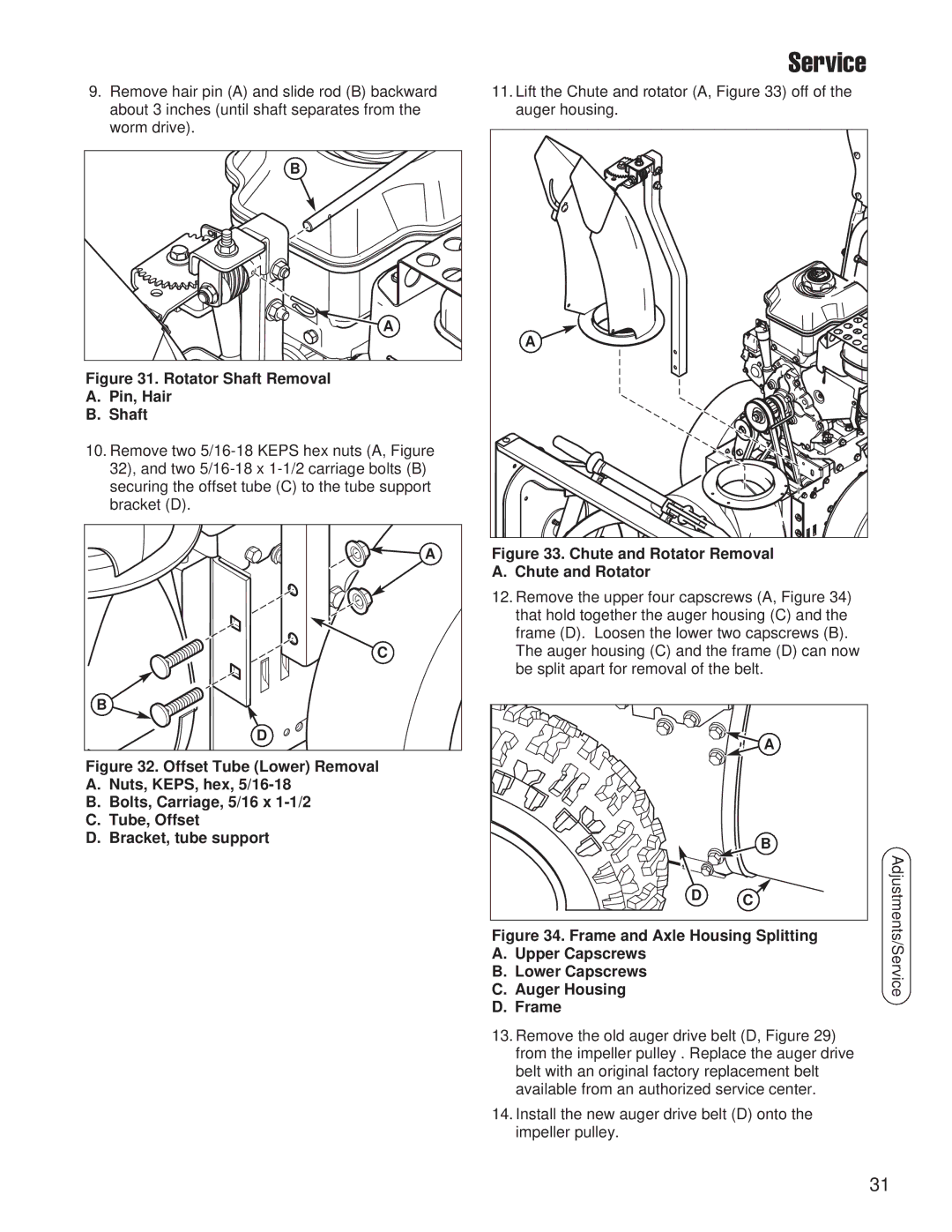
11.Lift the Chute and rotator (A, Figure 33) off of the auger housing.
A |
Figure 33. Chute and Rotator Removal
A. Chute and Rotator
12.Remove the upper four capscrews (A, Figure 34) that hold together the auger housing (C) and the frame (D). Loosen the lower two capscrews (B).
The auger housing (C) and the frame (D) can now be split apart for removal of the belt.
| A |
| B |
D | C |
|
Figure 34. Frame and Axle Housing Splitting
A.Upper Capscrews
B.Lower Capscrews
C.Auger Housing
D.Frame
13.Remove the old auger drive belt (D, Figure 29) from the impeller pulley . Replace the auger drive belt with an original factory replacement belt available from an authorized service center.
14.Install the new auger drive belt (D) onto the impeller pulley.
Adjustments/Service
31