ROOM 1 | ROOM 2 |
|
| ROOM 3 |
|
|
| ROOM 4 |
| ||
SMR1 Series | MR1 Series |
|
|
|
|
| +12V |
| CR1 |
| |
|
|
|
|
| GND | OUT | CR1 | ||||
IR Receivers | Micro IR Receivers |
|
|
|
|
| Connecting | ||||
| WALLMOUNT IRRECEIVER | WMR1 | WMR1 | OUT | PWR | Block | |||||
|
|
|
|
| IR Receiver | ||||||
|
|
|
|
|
| 7 Foot Quick | |||||
|
|
|
| +12V |
|
| Wall Mount |
|
| Connect Cable |
|
|
|
|
| +12V |
| IR Receiver |
|
|
| ||
|
|
|
|
|
|
|
|
| |||
|
|
| OUT | OUTPUT |
|
|
|
|
| ||
Cable |
|
| GND | GND |
|
| PS1 | 120 VAC |
|
| |
Red | Cable |
|
|
|
|
|
| ||||
|
|
|
|
|
|
| Satellite Receiver | ||||
| Stripe |
| Red |
|
|
|
| Power | (Unswitched; see NOTE 1) | ||
|
|
| Stripe |
|
|
|
| Supply |
|
|
|
+12V | OUT |
|
|
|
|
|
|
|
|
| |
+12V | OUT |
|
|
|
|
|
|
|
| ||
|
|
|
|
|
|
|
|
| E1 Emitter | ||
GND |
| GND |
|
|
|
|
| CB1 | |||
|
|
|
|
|
|
| |||||
|
|
|
|
|
|
|
|
|
| ||
Connecting Block |
| DVD | ||
|
|
|
|
|
|
| 7 Foot |
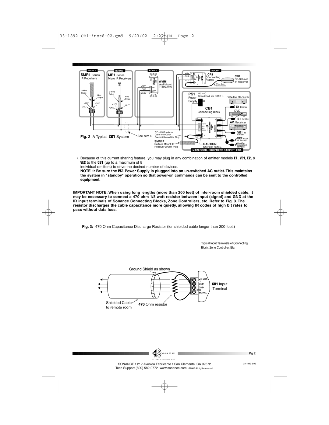
Fig. 2 A Typical CB1 System | See Item 4 | Cable with Quick |
Connect Stereo Mini Plug |
SMR1P
Surface Mount IR ![]()
Receiver w/Mini Plug
PWR |
|
|
| E1 Emitter | |
CONNECTINGBLOCK |
|
| AV Receiver | ||
+12VDC | CB1 ONEZONE | EMITTERS | |||
| |||||
GND |
|
|
|
| |
GND |
|
|
|
| |
SIGNAL |
|
|
| VE1 IR | |
IR RCVR |
|
|
| ||
|
|
| Emitter | ||
|
|
|
| ||
|
|
|
| VE2 Dual | |
|
|
|
| IR Emitter | |
CAUTION: | (to other | ||||
controlled | |||||
See text, item 5. | devices) | ||||
MAIN ROOM, EQUIPMENT CABINET, ETC.
7.Because of this current sharing feature, you may plug in any combination of emitter models E1, VE1, E2, & VE2 to the CB1 (up to a maximum of 8
individual emitters) to drive the desired number of devices.
NOTE 1: Be sure the PS1 Power Supply is plugged into an
IMPORTANT NOTE: When using long lengths (more than 200 feet) of
Fig. 3: 470 Ohm Capacitance Discharge Resistor (for shielded cable longer than 200 feet.)
Typical Input Terminals of Connecting
Block, Zone Controller, Etc.
Ground Shield as shown
|
| +12 VDC | CB1 Input | |
|
| |||
|
|
|
| |
|
| GND | ||
|
| |||
|
| GND | Terminal | |
|
| |||
|
|
|
| |
|
| SIGNAL |
| |
Shielded Cable ![]() 470 Ohm resistor to remote room
470 Ohm resistor to remote room
|
|
|
| Pg |
| 2 |
|
|
|
|
|
|
| ||
|
|
|
| ||||
| SONANCE • 212 Avenida Fabricante • San Clemente, CA 92672 | ||||||
Tech Support (800)