I N S T R U C T I O N M A N U A L
S O N A M P ® 2 7 5 S E / 2 7 5 X 3 S E S T E R E O P O W E R A M P L I F I E R
Input Connections (Figure 1, #10)
Input signal is connected via the R and L RCA Input jacks. Make sure these are consistent with the R and L outputs from your preamplifier or source device.
Output Connections (Figure 1, #10)
The BBE SAT module included with the 275 SE/ 275X3 SE includes buffered R and L RCA output jacks. These can link additional power amplifiers to a single source component without using messy Y-cord adaptors.
Note: The buffered output signal is not BBE-processed.
Speaker Connectors (Figure 1, #16)
The speaker connectors on the Sonamp 275 SE/275X3 SE are hex style “5-way” binding posts. They can accept wire terminated in spade lugs, pins, single and double banana connectors as well as bare wire.
Caution: Do not over-tighten when using a hex nut-driver or socket.
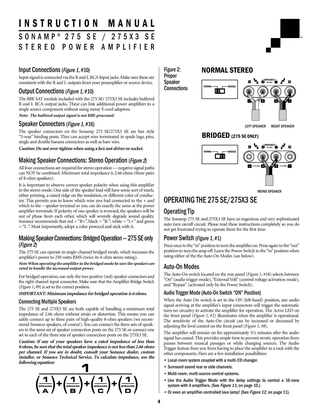
Making Speaker Connections: Stereo Operation (Figure 2)
All four connections are required for stereo operation — negative signal paths can NOT be combined. Minimum total impedance is 2.66 ohms (three pairs of 8-ohm speakers).
It is important to observe correct speaker polarity when using this amplifier in the stereo mode. One side of the speaker lead will have some sort of mark, either printing, a raised ridge on the insulation, or different color of conduc- tor. This permits you to know which wire you had connected to the + and which to the – speaker terminal so you can do exactly the same at the power amplifier terminals. If polarity of one speaker is reversed, the speakers will be out of phase from each other, which will severely degrade sound quality. Sonance recommends that red = “R+”, black = “R-“, white = “L+” and green = “L-”. Most importantly, adopt a color protocol and stick with it.
MakingSpeakerConnections:BridgedOperation—275SEonly
(Figure 2)
The 275 SE can operate in single-channel bridged mode, which increases the amplifier’s power to 250 watts RMS (twice its 4-ohm stereo rating).
Note When operating the amplifier in the bridged mode be sure the speakers are rated to handle the increased output power.
For bridged operation, use only the two positive (red) speaker connectors and the right channel input connector. Make sure that the Amplifier Bridge Switch (Figure 1, #9) is set to the correct position.
IMPORTANT: Minimum impedance for bridged operation is 6 ohms.
Connecting Multiple Speakers
The 275 SE and 275X3 SE are both capable of handling a minimum total impedance of 2.66 ohms without strain or distortion. This means you can safely connect up to three pairs of high-quality 8-ohm speakers (we recom- mend Sonance speakers, of course!). You can connect the three sets of speak- ers to the same set of speaker connection posts on the 275 SE or connect one set to each of the three sets of speaker connection posts on the 275X3 SE.
Caution: If any of your speakers have a rated impedance of less than 8 ohms, be sure that the total speaker impedance is not less than 2.66 ohms per channel. If you are in doubt, consult your Sonance dealer, custom installer, or Sonance Technical Service. To calculate impedance, use the following equation:
Figure 2: | NORMAL STEREO |
Proper | |
Speaker | |
Connections | |
LEFT SPEAKER RIGHT SPEAKER
BRIDGED (275 SE ONLY)
MONO SPEAKER
OPERATING THE 275 SE/275X3 SE
Operating Tip
The Sonamp 275 SE and 275X3 SE have an ingenious and very sophisticated auto turn on/off circuit. Please read these instructions completely so you do not get frustrated trying to operate them for the first time.
Power Switch (Figure 1, #1)
Press once to the“in”position to turn the amplifier on. Press again to the“out” position to turn the amp off. Leave the Power Switch in the“in”position when using either of the the Auto On Modes (see below).
Auto-On Modes
The Auto-On switch located on the rear panel (Figure 1, #18) selects between "On" (audio trigger mode), "External Volt" (control voltage activation mode), and "Bypass" (activated only by the Power Switch).
Audio Trigger Mode (Auto-On Switch “ON” Position)
When the Auto On switch is set to the ON (left-hand) position, any audio signal arriving at the amplifier’s input connectors will trigger the automatic turn-on circuitry to activate the amplifier for operation. The Active LED on the front panel (Figure 1, #2) illuminates when the amplifier is operational. The sensitivity of the Auto-On circuit can be increased or decreased by adjusting the level control on the front panel (Figure 1, #8).
The amplifier will remain on for approximately 3½ minutes after the audio signal has ceased. This provides ample time to prevent erratic operation from pauses between musical passages or while changing sources. The Audio Trigger feature frees you from having to place the amplifier in a rack with the other components. Here are a few installation possibilities:
•Local-room system coupled with a multi-CD changer.
•Surround sound rear or side channels.
•Multi-room, multi-source control systems.
•Use the Audio Trigger Mode with the delay settings to control a 16-zone system with 4 amplifiers. (See Figure 11, on page 10.)
•Or even an amplifier-controlled lava lamp! (See Figure 12, on page 11).