I N S T R U C T I O N M A N U A L
S O N A M P ® 2 7 5 S E / 2 7 5 X 3 S E S T E R E O P O W E R A M P L I F I E R
External Voltage Mode (Auto-On Switch"External Volt" Position)
The 275 SE/275X3 SE also feature a removable voltage input connector to connect other electronics with voltage control outputs. When the Auto-On switch is set to the“Voltage Trigger“(center) position,the voltage trigger mon- itors the voltage input connector (Figure 1, #19) and turns the amplifier ON when a voltage (either AC or DC) between 5V and 24V is detected.
Bypass Mode (Auto-On Switch "Bypass" position)
When the auto On switch is set to the BYPASS (right-hand) position, the Auto-On circuit is bypassed. In this mode, the amplifier is active any time the front-panel Power switch is in the "in" position.
Auto-On Delay Time Switches (Figure 1, #17)
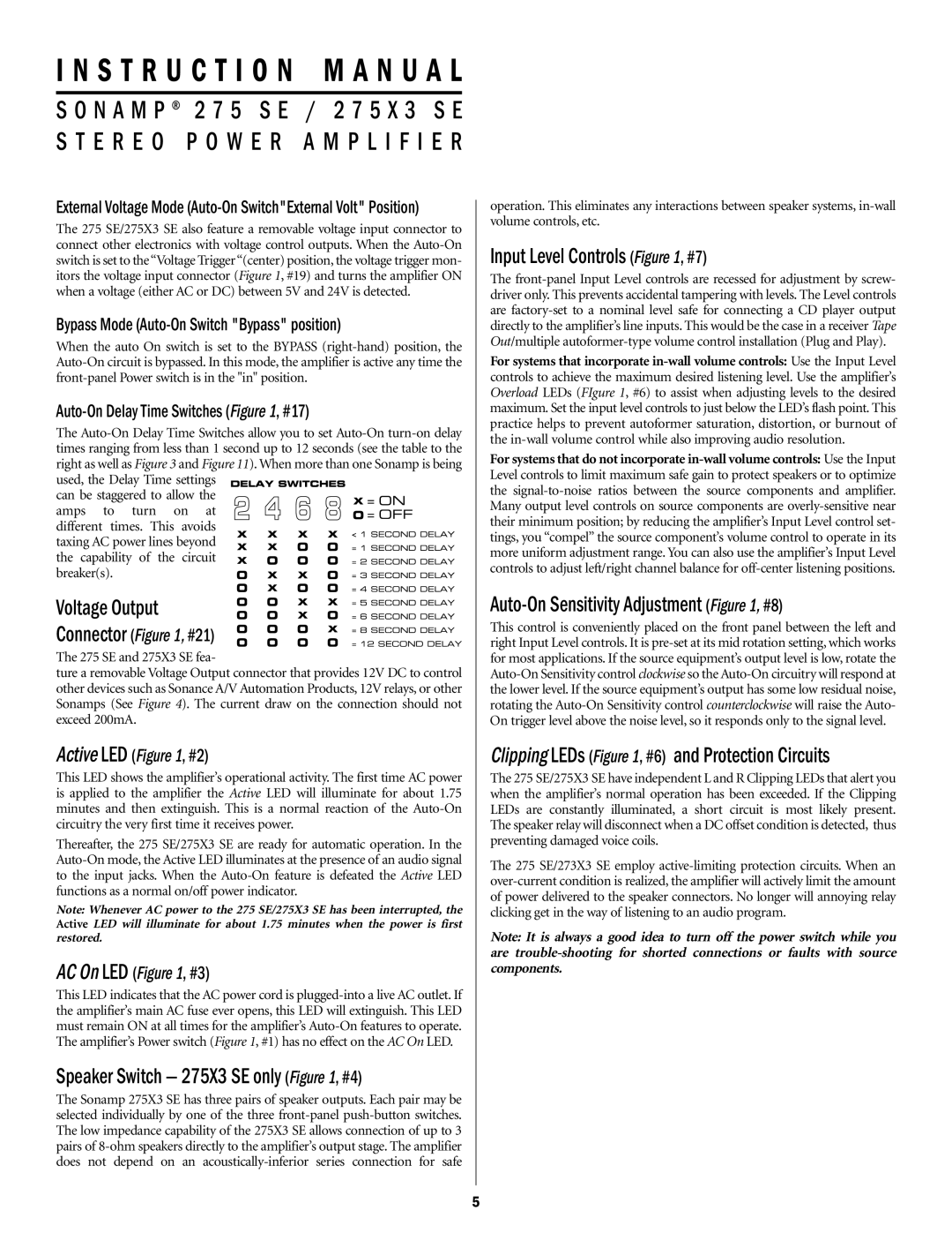
The Auto-On Delay Time Switches allow you to set Auto-On turn-on delay times ranging from less than 1 second up to 12 seconds (see the table to the right as well as Figure 3 and Figure 11). When more than one Sonamp is being used, the Delay Time settings 


can be staggered to allow the
amps to turn on at different times. This avoids
taxing AC power lines beyond
the capability of the circuit breaker(s).
Voltage Output
Connector (Figure 1, #21)
The 275 SE and 275X3 SE fea-
ture a removable Voltage Output connector that provides 12V DC to control other devices such as Sonance A/V Automation Products, 12V relays, or other Sonamps (See Figure 4). The current draw on the connection should not exceed 200mA.
Active LED (Figure 1, #2)
This LED shows the amplifier’s operational activity. The first time AC power is applied to the amplifier the Active LED will illuminate for about 1.75 minutes and then extinguish. This is a normal reaction of the Auto-On circuitry the very first time it receives power.
Thereafter, the 275 SE/275X3 SE are ready for automatic operation. In the Auto-On mode, the Active LED illuminates at the presence of an audio signal to the input jacks. When the Auto-On feature is defeated the Active LED functions as a normal on/off power indicator.
Note: Whenever AC power to the 275 SE/275X3 SE has been interrupted, the Active LED will illuminate for about 1.75 minutes when the power is first restored.
AC On LED (Figure 1, #3)
This LED indicates that the AC power cord is plugged-into a live AC outlet. If the amplifier’s main AC fuse ever opens, this LED will extinguish. This LED must remain ON at all times for the amplifier’s Auto-On features to operate. The amplifier’s Power switch (Figure 1, #1) has no effect on the AC On LED.
Speaker Switch — 275X3 SE only (Figure 1, #4)
The Sonamp 275X3 SE has three pairs of speaker outputs. Each pair may be selected individually by one of the three front-panel push-button switches. The low impedance capability of the 275X3 SE allows connection of up to 3 pairs of 8-ohm speakers directly to the amplifier’s output stage. The amplifier does not depend on an acoustically-inferior series connection for safe
operation. This eliminates any interactions between speaker systems, in-wall volume controls, etc.
Input Level Controls (Figure 1, #7)
The front-panel Input Level controls are recessed for adjustment by screw- driver only. This prevents accidental tampering with levels. The Level controls are factory-set to a nominal level safe for connecting a CD player output directly to the amplifier’s line inputs. This would be the case in a receiver Tape Out/multiple autoformer-type volume control installation (Plug and Play).
For systems that incorporate in-wall volume controls: Use the Input Level controls to achieve the maximum desired listening level. Use the amplifier’s Overload LEDs (FIgure 1, #6) to assist when adjusting levels to the desired maximum. Set the input level controls to just below the LED’s flash point. This practice helps to prevent autoformer saturation, distortion, or burnout of the in-wall volume control while also improving audio resolution.
For systems that do not incorporate in-wall volume controls: Use the Input Level controls to limit maximum safe gain to protect speakers or to optimize the signal-to-noise ratios between the source components and amplifier. Many output level controls on source components are overly-sensitive near their minimum position; by reducing the amplifier’s Input Level control set- tings, you “compel” the source component’s volume control to operate in its more uniform adjustment range. You can also use the amplifier’s Input Level controls to adjust left/right channel balance for off-center listening positions.
Auto-On Sensitivity Adjustment (Figure 1, #8)
This control is conveniently placed on the front panel between the left and right Input Level controls. It is pre-set at its mid rotation setting, which works for most applications. If the source equipment’s output level is low, rotate the Auto-On Sensitivity control clockwise so the Auto-On circuitry will respond at the lower level. If the source equipment’s output has some low residual noise, rotating the Auto-On Sensitivity control counterclockwise will raise the Auto- On trigger level above the noise level, so it responds only to the signal level.
Clipping LEDs (Figure 1, #6) and Protection Circuits
The 275 SE/275X3 SE have independent L and R Clipping LEDs that alert you when the amplifier’s normal operation has been exceeded. If the Clipping LEDs are constantly illuminated, a short circuit is most likely present. The speaker relay will disconnect when a DC offset condition is detected, thus preventing damaged voice coils.
The 275 SE/273X3 SE employ active-limiting protection circuits. When an over-current condition is realized, the amplifier will actively limit the amount of power delivered to the speaker connectors. No longer will annoying relay clicking get in the way of listening to an audio program.
Note: It is always a good idea to turn off the power switch while you are trouble-shooting for shorted connections or faults with source components.