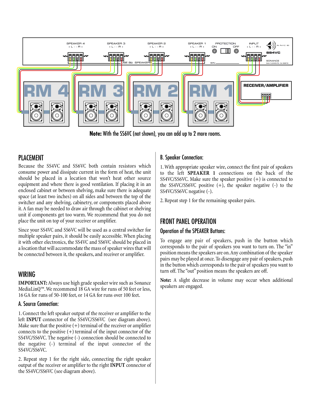
SS4VC, SS6VC specifications
Sonance SS6VC and SS4VC are innovative speaker systems designed to deliver exceptional audio performance and versatility for home audio applications. Renowned for their superior quality and advanced engineering, these speakers are perfect for both background music and high-fidelity listening experiences.The Sonance SS6VC is a 6-inch in-ceiling speaker that boasts a wide frequency response range, allowing it to reproduce crisp highs and rich lows. It features a specially designed polypropylene cone and a high-performance tweeter, ensuring you hear every note with clarity. With a power handling capability of up to 100 watts, the SS6VC is capable of filling larger spaces with sound, making it ideal for living rooms, entertainment areas, and outdoor patios.
On the other hand, the SS4VC is a smaller, 4-inch version that offers flexibility without compromising on audio quality. This speaker is perfect for smaller rooms or areas where space is a consideration, delivering impressive audio performance with a power handling capability of 75 watts. The SS4VC shares many design elements with its larger counterpart, such as the durable construction and refined components that contribute to its impressive sonic capabilities.
One of the standout features of both models is their easy installation process. The speakers are designed with a secure mounting system that allows for quick and straightforward installation, whether you choose to flush-mount them in ceilings or walls. Their low-profile design ensures that they blend seamlessly into any environment, minimizing visual distraction while enhancing the overall aesthetic of your space.
Moreover, both SS6VC and SS4VC are equipped with Sonance's innovative technology that optimizes audio dispersion, ensuring that sound is evenly distributed throughout the room. This feature allows for an immersive listening experience, whether you're hosting a party, watching a movie, or enjoying your favorite music.
Durability is another characteristic that sets the Sonance SS series apart. Constructed with high-quality materials, these speakers are designed to withstand various environmental conditions, making them suitable for indoor and outdoor use.
In summary, the Sonance SS6VC and SS4VC speakers represent a perfect blend of quality, performance, and versatility for today's audio enthusiasts. With their advanced features and user-friendly installation, they are an excellent choice for any home audio setup, promising an unparalleled listening experience.

