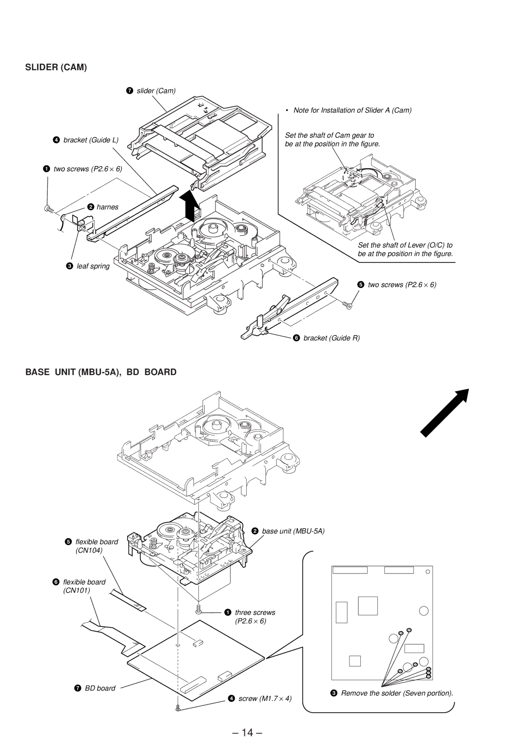
SLIDER (CAM)
7slider (Cam)
4 bracket (Guide L)
1 two screws (P2.6 × 6)
2 harnes
• Note for Installation of Slider A (Cam)
Set the shaft of Cam gear to be at the position in the figure.
3 leaf spring
BASE UNIT (MBU-5A), BD BOARD
5 flexible board (CN104)
6flexible board
(CN101)
7BD board
Set the shaft of Lever (O/C) to be at the position in the figure.
5 two screws (P2.6 × 6)
6 bracket (Guide R)
2base unit
1 three screws
(P2.6 × 6)
 3 Remove the solder (Seven portion). 4 screw (M1.7 × 4)
– 14 –