SECTION 3
DISASSEMBLY
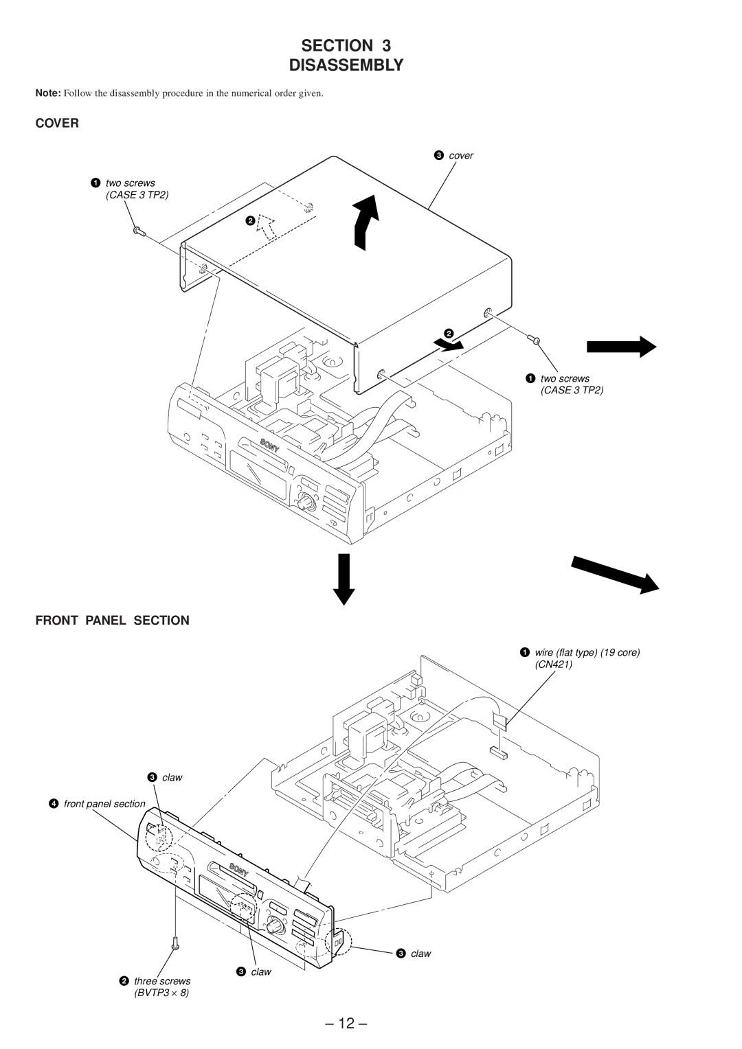
Note: Follow the disassembly procedure in the numerical order given.
COVER
1two screws
(CASE 3 TP2)
FRONT PANEL SECTION
3claw
4front panel section
2three screws (BVTP3 × 8)
3 cover
2
2
1 two screws (CASE 3 TP2)
1 wire (flat type) (19 core) (CN421)
3 claw
3claw
– 12 –
