| TABLE OF CONTENTS |
|
2 | ||
1. | SERVICING NOTES | 4 |
2. | GENERAL | 11 |
3. | DISASSEMBLY | 12 |
4. | TEST MODE | 16 |
5. | ELECTRICAL ADJUSTMENTS | 21 |
6.DIAGRAMS
IC Pin Function Description | 30 | |
Block Diagram – SERVO Section | 37 | |
Block Diagram – MAIN Section | 39 | |
Note for Printed Wiring Boards and |
| |
| Schematic Diagrams | 42 |
Printed Wiring Board – BD Board | 43 | |
Schematic Diagram – BD Board (1/2) | 45 | |
Schematic Diagram – BD Board (2/2) | 47 | |
Schematic Diagram – SW Board | 49 | |
Printed Wiring Board – SW Board | 49 | |
53 | ||
55 | ||
Schematic Diagram – MAIN Board (1/2) | 57 | |
| ||
| – MAIN Board (2/2), TRANS Board | 59 |
61 | ||
Schematic Diagram – PANEL/PANEL 2 Boards | 63 | |
7. | EXPLODED VIEWS | 66 |
8. | ELECTRICAL PARTS LIST | 70 |
SECTION 1
SERVICING NOTES
SAFETY
After correcting the original service problem, perform the follow- ing safety check before releasing the set to the customer:
Check the antenna terminals, metal trim, “metallized” knobs, screws, and all other exposed metal parts for AC leakage. Check leakage as described below.
LEAKAGE TEST
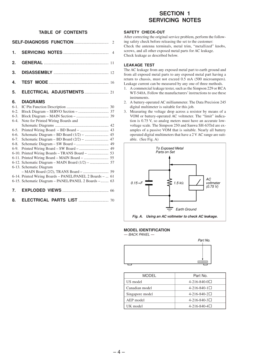
The AC leakage from any exposed metal part to earth ground and from all exposed metal parts to any exposed metal part having a return to chassis, must not exceed 0.5 mA (500 microampers). Leakage current can be measured by any one of three methods.
1.A commercial leakage tester, such as the Simpson 229 or RCA
2.A
3.Measuring the voltage drop across a resistor by means of a VOM or
To Exposed Metal
Parts on Set
0.15 ∝F |
|
|
| 1.5 k Ω | AC |
|
|
| voltmeter | ||
|
|
|
|
| (0.75 V) |
|
|
|
|
|
|
Earth Ground
Fig. A. Using an AC voltmeter to check AC leakage.
MODEL IDENTIFICATION
— BACK PANEL —
Part No.
MODEL | Part No. |
|
|
US model | |
|
|
Canadian model | |
|
|
Singapore model | |
|
|
AEP model | |
|
|
UK model |
– 4 –