1INCOM (intercom) LEVEL control
This contorl adjusts the audio volume of the intercom.
2TALK switch
This switch selects the voice transmission mode to the camera control unit (CCU).
ON: The cameraperson’s voice is transmitted to the CCU.
OFF: The cameraperson’s voice is not transmitted to the CCU.
REMOTE: Transmission of the cameraperson’s voice to the CCU is turned on or off by a signal input by the RET CONT connector.
3PGM (program) LEVEL control
This control adjusts the program audio volume.
4PROD(producer)/ENG(engineer) switch Set this switch to the intercom line to be used.
PROD: Producer’s line
ENG: Engineer’s line
5CALL button
When you press this button, the red tally lamps on the CCU and in the viewfinder light up. Use this button to call the CCU operator.
6Triax connector
Connect a
7RET (return video) 2 button
While this button is pressed, the return video signal 2 from the CCU appears in the viewfinder.
8RET (return video) 1 button
While this button is pressed, the return video signal 1 from the CCU appears in the viewfinder.
9EARPHONE jack (minijack)
Connect an
!º INCOM (intercom)/PGM (program) connector (XLR-type, 5-pin)
Connect a headset to this connector to transmit/receive over the intercom and monitor the program audio. When the microphone you are going to use is a dynamic microphone, detach the side panel on the CA- 755/755P and set the INCOM MIC switch to D (dymamic). This switch is factory set to C (carbon).
For details, see “Internal Switch Settings” (next page).
!¡ DC IN 11.5-17.0 V connector (XLR-type, 4-pin)
Connect an
Note
When a CCU is connected and an external power supply is connected to the DC IN connector, power supplied from the DC IN connector takes precedence over other power sources.
!™ Accessory mounting holes
Attach the supplied cable clamp or other accessories to this section.
Note
Attaching a
For details, contact Sony Service Personnel.
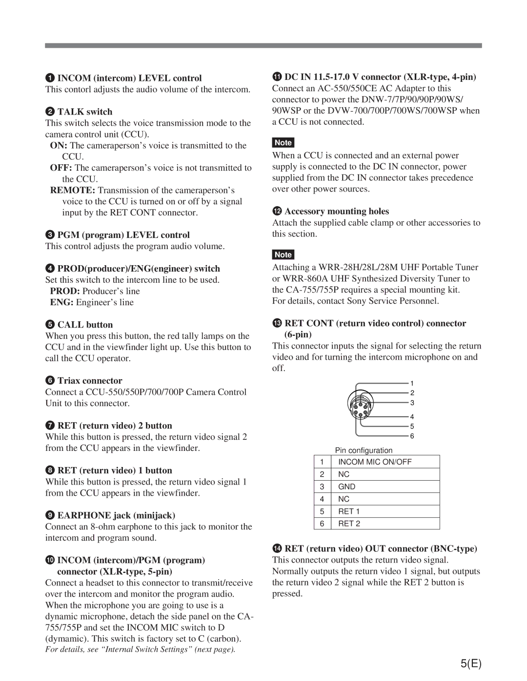
!£ RET CONT (return video control) connector (6-pin)
This connector inputs the signal for selecting the return video and for turning the intercom microphone on and off.
1
2 ![]()
![]() 3
3
![]()
![]() 4
4
5
6
| Pin configuration |
1 | INCOM MIC ON/OFF |
|
|
2 | NC |
|
|
3 | GND |
|
|
4 | NC |
|
|
5 | RET 1 |
|
|
6 | RET 2 |
!¢ RET (return video) OUT connector (BNC-type)
This connector outputs the return video signal. Normally outputs the return video 1 signal, but outputs the return video 2 signal while the RET 2 button is pressed.
5(E)
