CDX-GT50W/GT500/GT500EE/GT550
Power amplifier section
Outputs: | Speaker outputs (sure seal connectors) |
Speaker impedance: | 4 – 8 ohms |
Maximum power output: | 52 W ⋅ 4 (at 4 ohms) |
General
Outputs: | Audio outputs terminal (front/rear) |
| Subwoofer output terminal (mono) |
| Power antenna relay control terminal |
| Power amplifier control terminal |
Inputs: | Telephone ATT control terminal |
| Illumination control terminal |
| BUS control input terminal |
| BUS audio input/AUX IN terminal |
| Remote controller input terminal |
| Antenna input terminal |
Tone controls: | Low: ±10 dB at 60 Hz or 100 Hz (XPLOD) |
| Mid: ±10 dB at 500 Hz or 1 kHz (XPLOD) |
| High: ±10 dB at 10 kHz or 12.5 kHz (XPLOD) |
Power requirements: | 12 V DC car battery (negative ground) |
Dimensions: | Approx. 178 ⋅ 50 ⋅ 181 mm |
| (7 1/8 ⋅ 2 ⋅ 7 1/4 in) (w/h/d) |
Mounting dimensions: | Approx. 182 ⋅ 53 ⋅ 162 mm |
| (7 1/4 ⋅ 2 1/8 ⋅ 6 1/2 in) (w/h/d) |
Mass: | Approx. 1.2 kg (2 lb 11 oz) |
Supplied accessories: | Parts for installation and connections (1 set) |
| Card remote commander: |
Design and specifications are subject to change without notice.
NOTES ON HANDLING THE OPTICAL
The laser diode in the optical
During repair, pay attention to electrostatic breakdown and also use the procedure in the printed matter which is included in the repair parts.
The flexible board is easily damaged and should be handled with care.
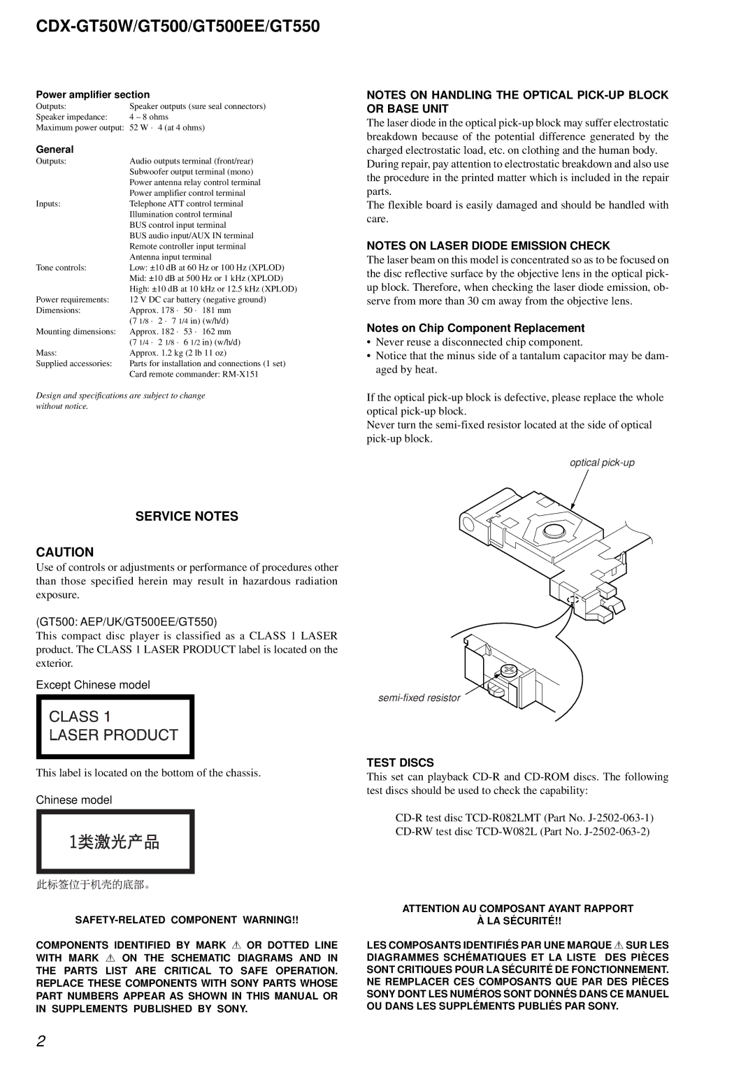
NOTES ON LASER DIODE EMISSION CHECK
The laser beam on this model is concentrated so as to be focused on the disc reflective surface by the objective lens in the optical pick- up block. Therefore, when checking the laser diode emission, ob- serve from more than 30 cm away from the objective lens.
Notes on Chip Component Replacement
•Never reuse a disconnected chip component.
•Notice that the minus side of a tantalum capacitor may be dam- aged by heat.
If the optical
Never turn the
optical
SERVICE NOTES
CAUTION
Use of controls or adjustments or performance of procedures other than those specified herein may result in hazardous radiation exposure.
(GT500: AEP/UK/GT500EE/GT550)
This compact disc player is classified as a CLASS 1 LASER product. The CLASS 1 LASER PRODUCT label is located on the exterior.
Except Chinese model
This label is located on the bottom of the chassis.
Chinese model
TEST DISCS
This set can playback
COMPONENTS IDENTIFIED BY MARK 0 OR DOTTED LINE WITH MARK 0 ON THE SCHEMATIC DIAGRAMS AND IN
THE PARTS LIST ARE CRITICAL TO SAFE OPERATION. REPLACE THESE COMPONENTS WITH SONY PARTS WHOSE PART NUMBERS APPEAR AS SHOWN IN THIS MANUAL OR IN SUPPLEMENTS PUBLISHED BY SONY.
ATTENTION AU COMPOSANT AYANT RAPPORT
À LA SÉCURITÉ!!
LES COMPOSANTS IDENTIFIÉS PAR UNE MARQUE 0 SUR LES
DIAGRAMMES SCHÉMATIQUES ET LA LISTE DES PIÈCES SONT CRITIQUES POUR LA SÉCURITÉ DE FONCTIONNEMENT. NE REMPLACER CES COMPOSANTS QUE PAR DES PIÈCES SONY DONT LES NUMÉROS SONT DONNÉS DANS CE MANUEL OU DANS LES SUPPLÉMENTS PUBLIÉS PAR SONY.
2