CDX-GT50W/GT500/GT500EE/GT550
• CDX-GT500EE
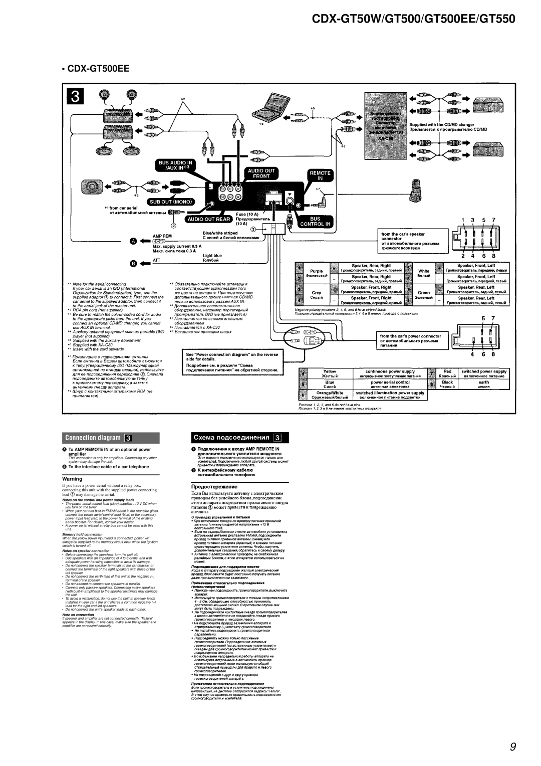
Connection diagram
ATo AMP REMOTE IN of an optional power amplifier
This connection is only for amplifiers. Connecting any other system may damage the unit.
BTo the interface cable of a car telephone
Warning
If you have a power aerial without a relay box, connecting this unit with the supplied power connecting lead 3 may damage the aerial.
Notes on the control and power supply leads
•The power aerial control lead (blue) supplies +12 V DC when you turn on the tuner.
•When your car has
•A power aerial without a relay box cannot be used with this unit.
Memory hold connection
When the yellow power input lead is connected, power will always be supplied to the memory circuit even when the ignition switch is turned off.
Notes on speaker connection
•Before connecting the speakers, turn the unit off.
•Use speakers with an impedance of 4 to 8 ohms, and with adequate power handling capacities to avoid its damage.
•Do not connect the speaker terminals to the car chassis, or connect the terminals of the right speakers with those of the left speaker.
•Do not connect the earth lead of this unit to the negative
•Do not attempt to connect the speakers in parallel.
•Connect only passive speakers. Connecting active speakers (with
•To avoid a malfunction, do not use the
•Do not connect the unit’s speaker leads to each other.
Note on connection
If speaker and amplifier are not connected correctly, “Failure” appears in the display. In this case, make sure the speaker and amplifier are connected correctly.
9