SECTION 3
CIRCUIT ADJUSTMENT
|
+4.5V ADJUSTMENT
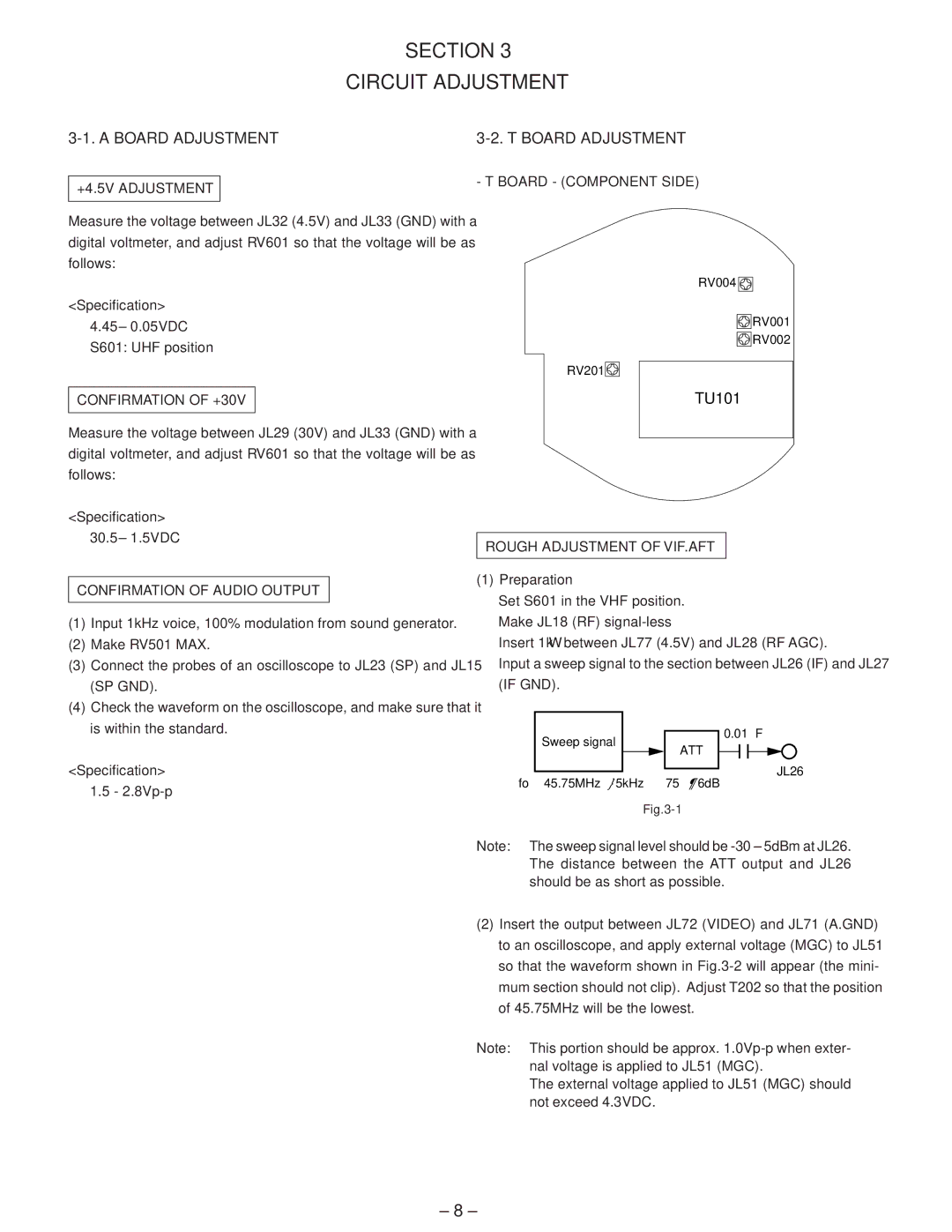
- T BOARD - (COMPONENT SIDE)
Measure the voltage between JL32 (4.5V) and JL33 (GND) with a digital voltmeter, and adjust RV601 so that the voltage will be as follows:
<Specification>
4.45± 0.05VDC S601: UHF position
CONFIRMATION OF +30V
Measure the voltage between JL29 (30V) and JL33 (GND) with a digital voltmeter, and adjust RV601 so that the voltage will be as follows:
<Specification> 30.5 ± 1.5VDC
CONFIRMATION OF AUDIO OUTPUT
(1)Input 1kHz voice, 100% modulation from sound generator.
(2)Make RV501 MAX.
(3)Connect the probes of an oscilloscope to JL23 (SP) and JL15 (SP GND).
(4)Check the waveform on the oscilloscope, and make sure that it is within the standard.
<Specification> 1.5 -
RV004
RV001
RV002
RV201
TU101
ROUGH ADJUSTMENT OF VIF.AFT
(1)Preparation
Set S601 in the VHF position.
Make JL18 (RF)
Insert 1kΩ between JL77 (4.5V) and JL28 (RF AGC).
Input a sweep signal to the section between JL26 (IF) and JL27 (IF GND).
|
| Sweep signal |
|
| 0.01∝F | |||
|
|
|
|
| ||||
|
|
|
| ATT |
|
|
| JL26 |
|
|
|
|
|
| |||
|
|
|
|
|
|
|
| |
|
|
|
|
|
|
|
| |
fo |
| 45.75MHz }5kHz 75 ¶ 6dB | ||||||
|
|
| ||||||
Note: | The sweep signal level should be | |||||||
| The distance between the ATT output and JL26 | |||||||
| should be as short as possible. | |||||||
(2)Insert the output between JL72 (VIDEO) and JL71 (A.GND) to an oscilloscope, and apply external voltage (MGC) to JL51 so that the waveform shown in
Note: This portion should be approx.
The external voltage applied to JL51 (MGC) should not exceed 4.3VDC.
– 8 –