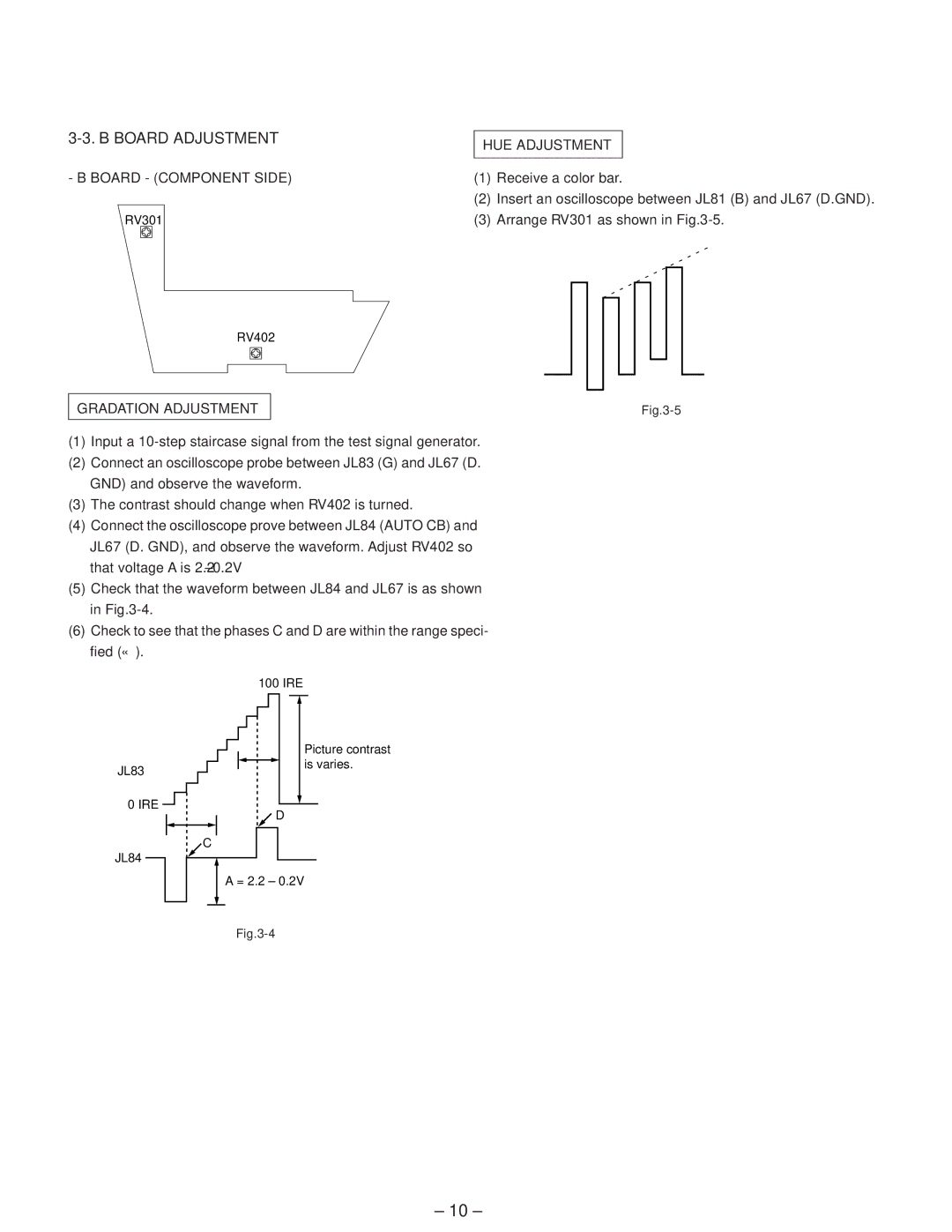
3-3. B BOARD ADJUSTMENT
HUE ADJUSTMENT
- B BOARD - (COMPONENT SIDE) | (1) | Receive a color bar. |
| (2) | Insert an oscilloscope between JL81 (B) and JL67 (D.GND). |
RV301 | (3) | Arrange RV301 as shown in |
RV402
GRADATION ADJUSTMENT
(1)Input a
(2)Connect an oscilloscope probe between JL83 (G) and JL67 (D. GND) and observe the waveform.
(3)The contrast should change when RV402 is turned.
(4)Connect the oscilloscope prove between JL84 (AUTO CB) and
JL67 (D. GND), and observe the waveform. Adjust RV402 so that voltage A is 2.2±0.2V
(5)Check that the waveform between JL84 and JL67 is as shown in
(6)Check to see that the phases C and D are within the range speci- fied (↔).
|
| 100 IRE | ||||
|
|
|
|
|
|
|
|
|
|
|
| Picture contrast | |
|
|
|
|
| ||
|
|
|
|
| ||
JL83 |
|
|
|
| is varies. | |
|
|
|
| |||
|
|
|
|
|
| |
|
|
|
|
|
|
|
0 IRE
![]() D
D
C
JL84
A = 2.2 ± 0.2V
– 10 –
