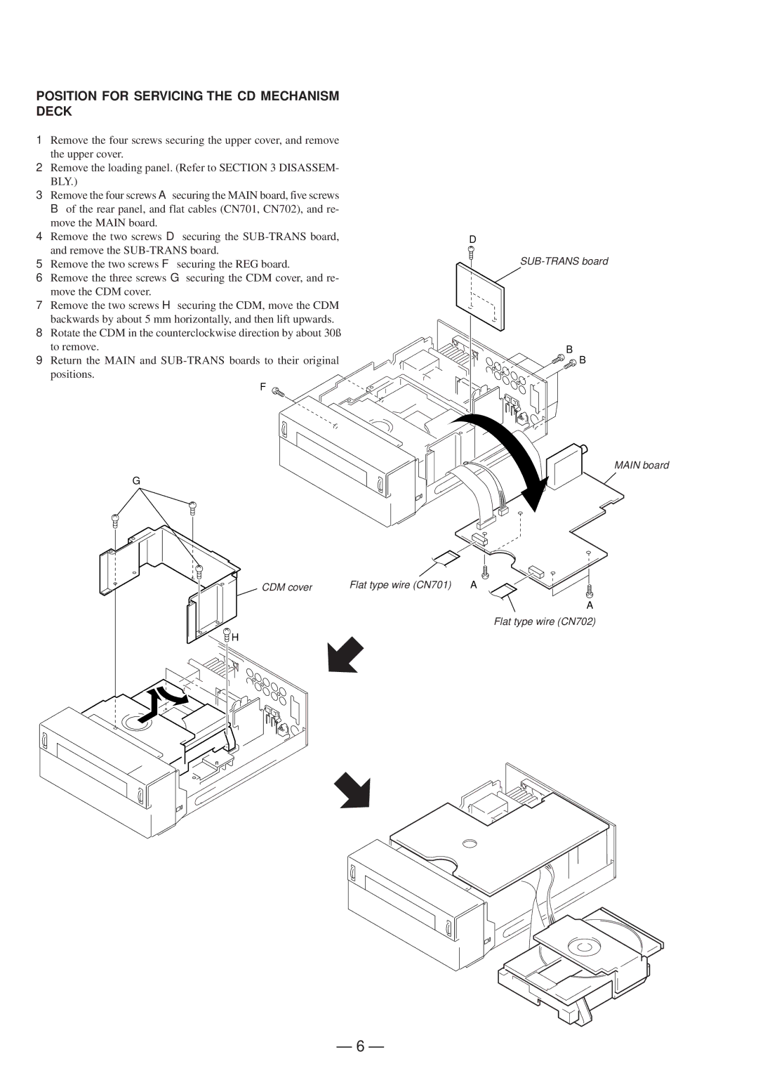
POSITION FOR SERVICING THE CD MECHANISM DECK
1Remove the four screws securing the upper cover, and remove the upper cover.
2Remove the loading panel. (Refer to SECTION 3 DISASSEM- BLY.)
3Remove the four screws Asecuring the MAIN board, five screws
Bof the rear panel, and flat cables (CN701, CN702), and re- move the MAIN board.
4 Remove the two screws D securing the | D |
and remove the |
|
5 Remove the two screws F securing the REG board. |
|
6Remove the three screws G securing the CDM cover, and re- move the CDM cover.
7Remove the two screws H securing the CDM, move the CDM backwards by about 5 mm horizontally, and then lift upwards.
8Rotate the CDM in the counterclockwise direction by about 30˚
to remove.
9Return the MAIN and
F
G
B
B
MAIN board
CDM cover | Flat type wire (CN701) A |
A
Flat type wire (CN702)
H
– 6 –
