Self-Diagnostic Screen Display
For errors with symptoms such as “power sometimes shuts off” or “screen sometimes goes out” that cannot be confirmed, it is possible to bring up past occurrences of failure on the screen for confirmation.
To Bring Up Screen Test
In standby mode, press buttons on the Remote Commander sequentially, in rapid succession, as shown below:
Display |
|
|
| Channel 5 |
|
|
|
| Sound Volume - |
| Power ON | |
|
|
|
|
|
|
|
| |||||
|
|
|
|
|
|
|
|
|
|
|
| Note that this differs from entering the Service Mode (Sound Volume |
|
|
|
| |||||||||
|
|
|
|
|
|
|
|
|
|
| ||
|
| SELF DIAGNOSTIC |
|
|
|
|
|
|
|
| ||
| 2: | +B OCP | 0 |
|
|
|
|
|
| |||
| 3: | +B OVP | N/A |
|
|
|
| |||||
| 4: | VSTOP | 0 |
|
|
| Numeral “0” means that no fault was detected. | |||||
|
|
|
|
| ||||||||
| 5: | AKB | 1 |
|
|
| Numeral “1” means a fault was detected one time only. | |||||
|
|
|
|
| ||||||||
| 101: | WDT | N/A |
|
|
|
| |||||
|
|
|
|
|
|
|
|
|
|
|
|
|
+
).
Handling of Self-Diagnostic Screen Display
Since the diagnostic results displayed on the screen are not automatically cleared, always check the
Unless the result display is cleared to “0”, the
Clearing the Result Display
To clear the result display to “0”, press buttons on the Remote Commander sequentially when the diagnostic screen is displayed, as shown below:
Channel
8![]()
![]()
![]() ENTER
ENTER
Quitting the Self-Diagnostic Screen
To quit the entire
|
|
|
| M BOARD | A BOARD |
|
| M BOARD |
|
|
|
|
| M BOARD | |||||
|
|
|
| IC001 | IC561 |
|
| IC001 |
|
|
|
|
| IC002 | |||||
|
|
| Y/CHROMA JUNGLE | V. OUT |
|
| SYSTEM |
|
|
|
|
| MEMORY | ||||||
FROM |
|
|
|
|
|
|
|
|
|
|
|
|
|
|
|
|
|
| |
C BOARD |
| 51 |
|
|
|
|
|
|
|
|
|
|
|
|
|
| |||
|
| REF 3 |
|
| 53 |
|
|
|
|
|
| 5 BDA |
| ||||||
|
|
|
|
|
|
|
|
|
| ||||||||||
IC702 PIN 5 |
|
|
|
|
| 78 |
|
|
|
|
|
|
| ||||||
|
|
|
|
|
|
|
|
|
|
|
| ||||||||
FROM |
| 72 |
|
|
|
|
|
|
|
|
|
|
|
|
|
|
| ||
A BOARD |
|
|
|
|
|
|
|
|
|
|
|
|
|
|
| ||||
|
|
|
|
|
|
|
|
|
|
|
|
|
|
| |||||
|
|
|
|
|
|
|
|
|
|
|
|
| |||||||
IC501 |
|
|
|
|
|
|
|
|
|
|
|
| DISPLAY | ||||||
|
|
|
|
|
|
|
|
|
|
|
| ||||||||
|
|
|
|
|
|
|
|
|
|
|
|
|
| ||||||
PIN 1 |
|
|
|
|
|
|
|
|
|
|
|
|
|
| |||||
|
|
|
|
|
|
|
|
|
|
|
|
|
|
|
|
|
| ||
|
|
|
|
|
|
|
|
|
|
|
|
|
|
|
|
|
|
|
|
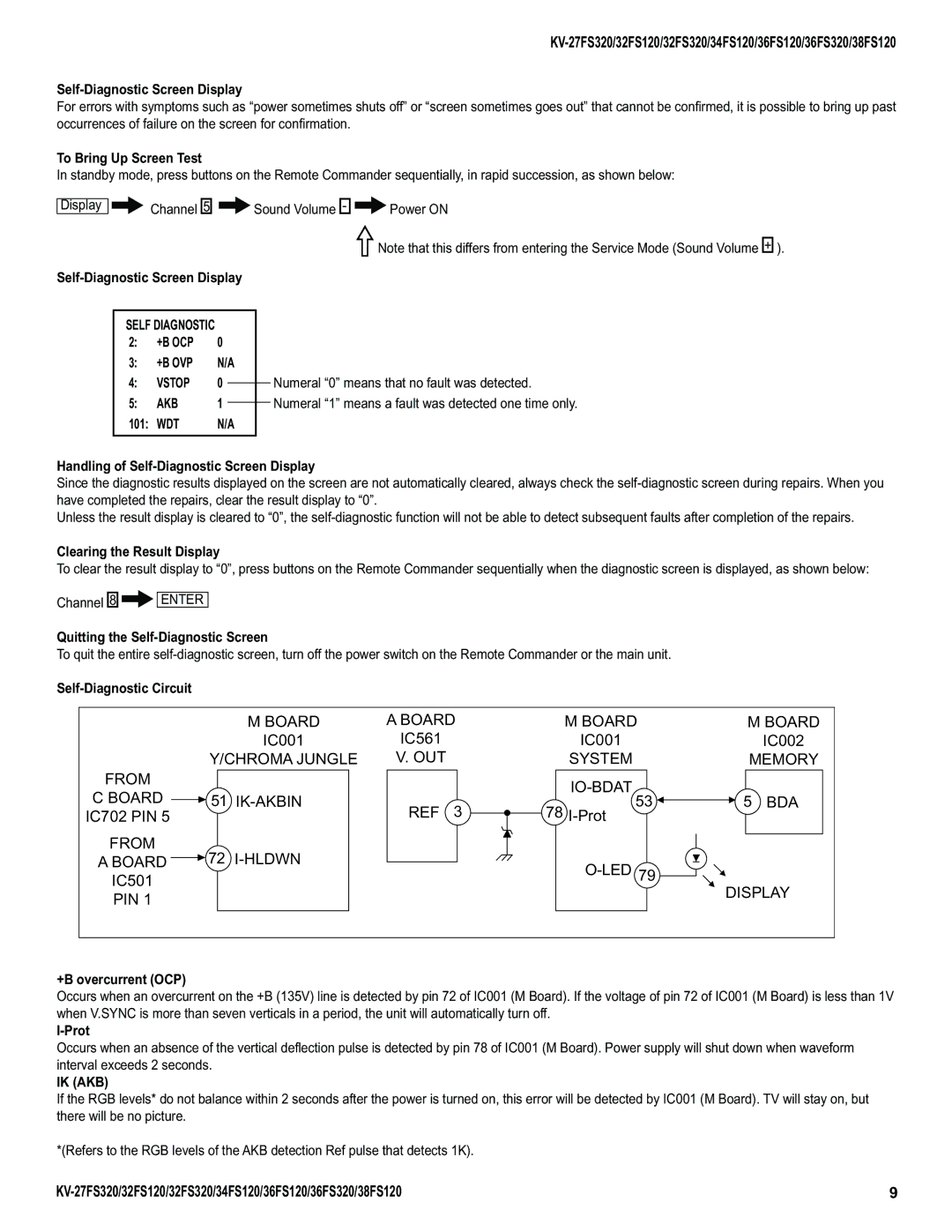
+B overcurrent (OCP)
Occurs when an overcurrent on the +B (135V) line is detected by pin 72 of IC001 (M Board). If the voltage of pin 72 of IC001 (M Board) is less than 1V when V.SYNC is more than seven verticals in a period, the unit will automatically turn off.
I-Prot
Occurs when an absence of the vertical deflection pulse is detected by pin 78 of IC001 (M Board). Power supply will shut down when waveform interval exceeds 2 seconds.
IK (AKB)
If the RGB levels* do not balance within 2 seconds after the power is turned on, this error will be detected by IC001 (M Board). TV will stay on, but there will be no picture.
*(Refers to the RGB levels of the AKB detection Ref pulse that detects 1K).
9 |
