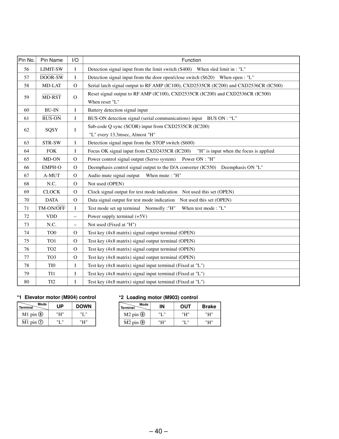
Pin No. |
| Pin Name | I/O |
|
| Function |
| ||||||
|
|
|
|
|
|
|
|
|
|
| |||
56 |
| I | Detection signal input from the limit switch (S400) | When sled limit in : "L" | |||||||||
|
|
|
|
|
|
|
|
|
|
| |||
57 |
|
|
|
|
|
| I | Detection signal input from the door open/close switch (S620) | When open : "L" | ||||
|
|
|
| ||||||||||
|
|
|
|
|
|
|
|
|
| ||||
58 |
| O | Serial latch signal output to RF AMP (IC100), CXD2535CR (IC200) and CXD2536CR (IC500) | ||||||||||
|
|
|
|
|
|
|
|
|
| ||||
|
|
|
|
|
|
|
|
| Reset signal output to RF AMP (IC100), CXD2535CR (IC200) and CXD2536CR (IC500) | ||||
59 |
| O | |||||||||||
| When reset "L" |
|
|
|
| ||||||||
|
|
|
|
|
|
|
|
|
|
|
|
| |
|
|
|
|
|
|
|
|
|
|
|
|
| |
60 |
|
| I | Battery detection signal input |
|
|
| ||||||
|
|
|
|
|
|
|
|
|
| ||||
61 |
|
|
|
|
|
| I | ||||||
|
| ||||||||||||
62 |
|
| SQSY | I |
| ||||||||
|
| "L" every 13.3msec, Almost "H" |
|
|
| ||||||||
|
|
|
|
|
|
|
|
|
|
|
| ||
|
|
|
|
|
|
|
|
|
|
|
| ||
63 |
|
|
| I | Detection signal input from the STOP switch (S600) |
|
| ||||||
|
|
|
|
|
|
|
|
|
|
| |||
64 |
|
| FOK | I | Focus OK signal input from CXD2435CR (IC200) | "H" is input when the focus is applied | |||||||
|
|
|
|
|
|
|
|
|
|
|
| ||
65 |
|
| O | Power control signal output (Servo system) | Power ON : "H" |
| |||||||
|
|
|
|
|
|
|
|
|
|
| |||
66 |
| O | Deemphasis control signal output to the D/A converter (IC550) | Deemphasis ON "L" | |||||||||
|
|
|
|
|
|
|
|
|
|
|
|
| |
67 |
|
| O | Audio mute signal output | When mute : "H" |
|
| ||||||
|
|
|
|
|
|
|
|
|
|
|
|
|
|
68 |
|
| N.C. | O | Not used (OPEN) |
|
|
|
| ||||
|
|
|
|
|
|
|
|
|
|
| |||
69 |
|
| CLOCK | O | Clock signal output for test mode indication | Not used this set (OPEN) | |||||||
70 |
|
| DATA | O | Data signal output for test mode indication | Not used this set (OPEN) | |||||||
|
|
|
|
|
|
|
|
|
|
|
| ||
71 |
|
|
| I | Test mode set up terminal | Normolly :"H" | When test mode : "L" | ||||||
| |||||||||||||
|
|
|
|
|
|
|
|
|
|
|
|
| |
72 |
|
| VDD | – | Power supply terminal (+5V) |
|
|
| |||||
73 |
|
| N.C. | – | Not used (Fixed at "H") |
|
|
|
| ||||
|
|
|
|
|
|
|
|
|
|
|
| ||
74 |
|
| TO0 | O | Test key (4x8 matrix) signal output terminal (OPEN) |
|
| ||||||
|
|
|
|
|
|
|
|
|
|
|
| ||
75 |
|
| TO1 | O | Test key (4x8 matrix) signal output terminal (OPEN) |
|
| ||||||
|
|
|
|
|
|
|
|
|
|
|
| ||
76 |
|
| TO2 | O | Test key (4x8 matrix) signal output terminal (OPEN) |
|
| ||||||
|
|
|
|
|
|
|
|
|
|
|
| ||
77 |
|
| TO3 | O | Test key (4x8 matrix) signal output terminal (OPEN) |
|
| ||||||
|
|
|
|
|
|
|
|
|
|
| |||
78 |
|
| TI0 | I | Test key (4x8 matrix) signal input terminal (Fixed at "L") |
| |||||||
|
|
|
|
|
|
|
|
|
|
| |||
79 |
|
| TI1 | I | Test key (4x8 matrix) signal input terminal (Fixed at "L") |
| |||||||
|
|
|
|
|
|
|
|
|
|
| |||
80 |
|
| TI2 | I | Test key (4x8 matrix) signal input terminal (Fixed at "L") |
| |||||||
|
|
|
|
|
|
|
|
|
|
|
|
|
|
*1 Elevator motor (M904) control
|
| Mode | UP | DOWN |
Terminal | ||||
| M1 pin 6 | "H" | "L" | |
|
|
|
|
|
|
| pin 7 | "L" | "H" |
| M1 | |||
*2 Loading motor (M903) control
|
| Mode | IN | OUT | Brake |
Terminal | |||||
| M2 pin 8 | "L" | "H" | "H" | |
|
| pin 9 | "H" | "L" | "H" |
| M2 | ||||
– 40 –
