| TABLE OF CONTENTS |
|
1. | GENERAL | 3 |
2. | DISASSEMBLY | 7 |
3.DIAGRAMS
Block Diagram | 11 | |
13 | ||
15 | ||
20 | ||
23 | ||
Schematic Diagram – Power Section | 26 | |
29 | ||
33 | ||
4. | EXPLODED VIEWS | 41 |
5. | ELECTRICAL PARTS LIST | 45 |
CAUTION
Use of controls or adjustments or performance of pro- cedures other than those specified herein may result in hazardous radiation exposure.
COMPONENTS IDENTIFIED BY MARK ! OR DOTTED LINE WITH MARK ! ON THE SCHEMATIC DIAGRAMS
AND IN THE PARTS LIST ARE CRITICAL TO SAFE OPERATION. REPLACE THESE COMPONENTS WITH SONY PARTS WHOSE PART NUMBERS APPEAR AS SHOWN IN THIS MANUAL OR IN SUPPLEMENTS PUB- LISHED BY SONY.
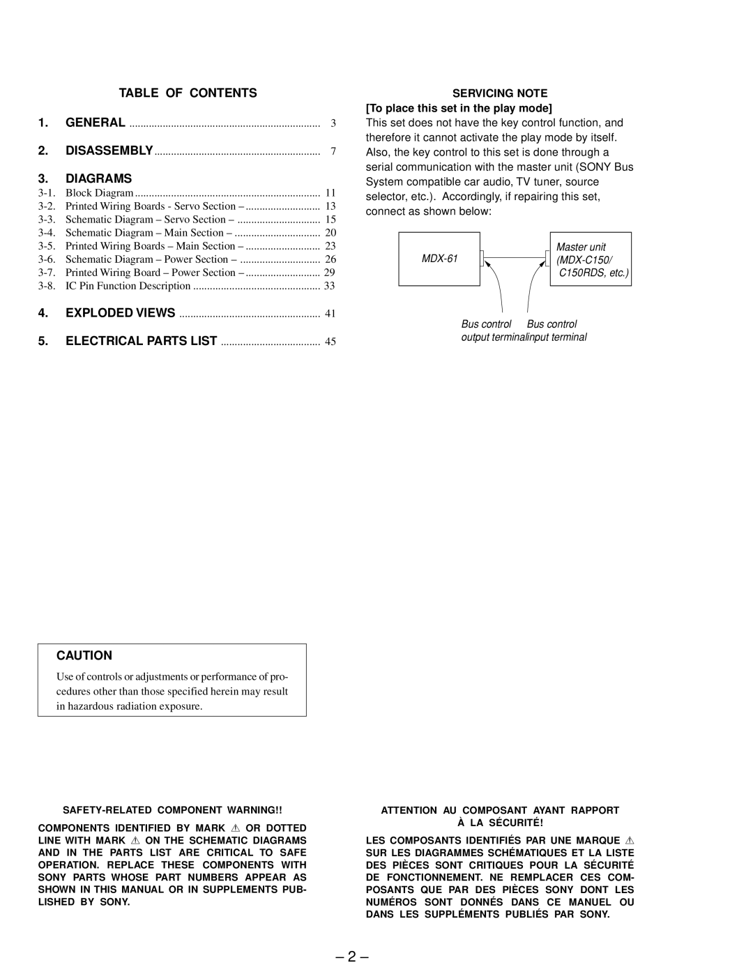
SERVICING NOTE [To place this set in the play mode]
This set does not have the key control function, and therefore it cannot activate the play mode by itself. Also, the key control to this set is done through a serial communication with the master unit (SONY Bus System compatible car audio, TV tuner, source selector, etc.). Accordingly, if repairing this set, connect as shown below:
|
|
| Master unit | |
|
|
| ||
|
|
|
| C150RDS, etc.) |
|
|
|
|
|
Bus control | Bus control | |||
output terminalinput terminal
ATTENTION AU COMPOSANT AYANT RAPPORT
À LA SÉCURITÉ!
LES COMPOSANTS IDENTIFIÉS PAR UNE MARQUE !
SUR LES DIAGRAMMES SCHÉMATIQUES ET LA LISTE DES PIÈCES SONT CRITIQUES POUR LA SÉCURITÉ DE FONCTIONNEMENT. NE REMPLACER CES COM- POSANTS QUE PAR DES PIÈCES SONY DONT LES NUMÉROS SONT DONNÉS DANS CE MANUEL OU DANS LES SUPPLÉMENTS PUBLIÉS PAR SONY.
– 2 –
