SECTION 2
DISASSEMBLY
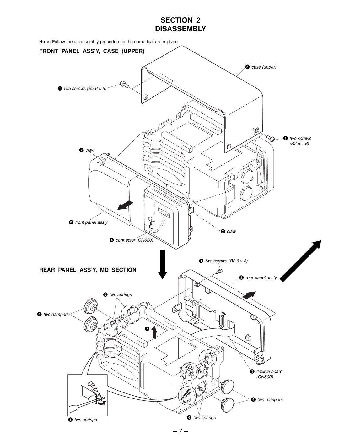
Note: Follow the disassembly procedure in the numerical order given.
FRONT PANEL ASS’Y, CASE (UPPER)
5 case (upper)
1 two screws (B2.6 ⋅ 6)
![]()
![]() 1 two screws (B2.6 ⋅ 6)
1 two screws (B2.6 ⋅ 6)
2claw
3 front panel ass’y
2 claw
4connector (CN620)
1 two screws (B2.6 ⋅ 8)
REAR PANEL ASS’Y, MD SECTION
2 rear panel ass’y
6 two springs
4 two dampers
7
3 flexible board (CN800)
4 two dampers
5 two springs | 6 two springs |
|
– 7 –