TABLE OF CONTENTS


1.

GENERAL


Location of controls

3


Installation

4


Connections

5

2.

DISASSEMBLY

9

3.ELECTRICAL ADJUSTMENTS

Test Mode

16

MD Section

16

Tuner Section

16

4.DIAGRAMS

4-1.

Block Diagram – SERVO Section

17

4-2.

Block Diagram – TUNER Section

18

4-3.

Block Diagram – MAIN Section

19

4-4.

Block Diagram – BUS CONTROL/


POWER SUPPLY Section

20

4-5.

Note for Printed Wiring Boards and


Schematic Diagrams

21

4-6.

Printed Wiring Boards


– SERVO Board (Component Side)/


SENSOR Board

22

4-7.

Printed Wiring Board


– SERVO Board (Conductor Side)

23

4-8. Schematic Diagram – SERVO Board (1/2)

24

4-9. Schematic Diagram – SERVO Board (2/2)

25

4-10.

Printed Wiring Board


– MAIN Board (Component Side)

26

4-11.

Printed Wiring Board


– MAIN Board (Conductor Side)

27

4-12.

Schematic Diagram – MAIN Board (1/3)

28

4-13.

Schematic Diagram – MAIN Board (2/3)

29

4-14.

Schematic Diagram – MAIN Board (3/3)

30

4-15.

Printed Wiring Board – SUB Board

32

4-16.

Schematic Diagram – SUB Board

33

4-17.

Printed Wiring Board – KEY Board

34

4-18.

Schematic Diagram – KEY Board

35

4-19. IC Pin Function Description

40

5.

EXPLODED VIEWS

50

6.

ELECTRICAL PARTS LIST

54

NOTES ON HANDLING THE OPTICAL PICK-UP BLOCK OR BASE UNIT

The laser diode in the optical pick-up block may suffer electro- static break-down because of the potential difference generated by the charged electrostatic load, etc. on clothing and the human body.

During repair, pay attention to electrostatic break-down and also use the procedure in the printed matter which is included in the repair parts.

The flexible board is easily damaged and should be handled with care.

NOTES ON LASER DIODE EMISSION CHECK

Never look into the laser diode emission from right avove when checking it for adustment. It is feared that you will lose your sight.

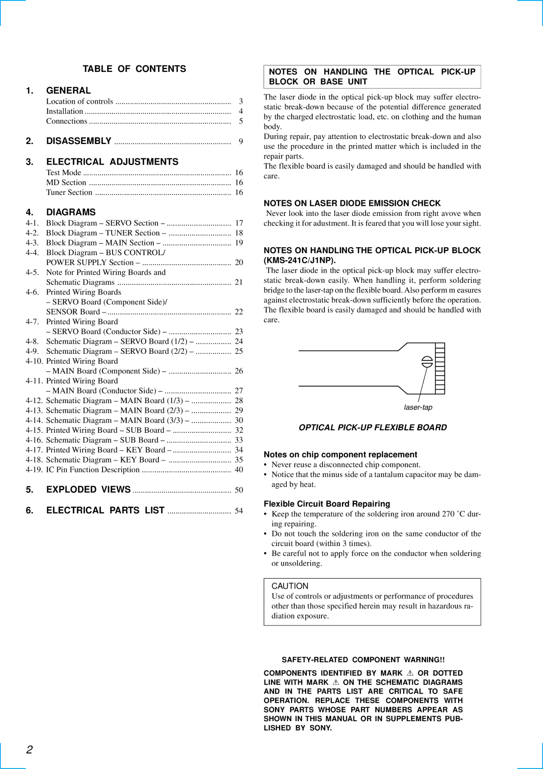
NOTES ON HANDLING THE OPTICAL PICK-UP BLOCK (KMS-241C/J1NP).

The laser diode in the optical pick-up block may suffer electro- static break-down easily. When handling it, perform soldering bridge to the laser-tap on the flexible board. Also perform m easures against electrostatic break-down sufficiently before the operation. The flexible board is easily damaged and should be handled with care.

laser-tap

OPTICAL PICK-UP FLEXIBLE BOARD

Notes on chip component replacement

Never reuse a disconnected chip component.

Notice that the minus side of a tantalum capacitor may be dam- aged by heat.

Flexible Circuit Board Repairing

Keep the temperature of the soldering iron around 270 ˚C dur- ing repairing.

Do not touch the soldering iron on the same conductor of the circuit board (within 3 times).

Be careful not to apply force on the conductor when soldering or unsoldering.

CAUTION

Use of controls or adjustments or performance of procedures other than those specified herein may result in hazardous ra- diation exposure.

SAFETY-RELATED COMPONENT WARNING!!

COMPONENTS IDENTIFIED BY MARK 0 OR DOTTED LINE WITH MARK 0 ON THE SCHEMATIC DIAGRAMS

AND IN THE PARTS LIST ARE CRITICAL TO SAFE OPERATION. REPLACE THESE COMPONENTS WITH SONY PARTS WHOSE PART NUMBERS APPEAR AS SHOWN IN THIS MANUAL OR IN SUPPLEMENTS PUB- LISHED BY SONY.

2

Page 2
Image 2
Sony MDX-C6500RX service manual Table of Contents General, Electrical Adjustments, Diagrams, Disassembly

MDX-C6500R, MDX-C6500RX specifications

The Sony MDX-C6500R and MDX-C6500RX are distinguished models in the realm of automotive audio systems, known for their innovative features and superior sound quality. Designed to enhance the driving experience, these units combine functionality with state-of-the-art technology, making them popular choices among car audio enthusiasts.

One of the standout features of the MDX-C6500R and MDX-C6500RX is their impressive sound output. Both models are equipped with a high-quality amplifier that delivers clear and powerful audio performance. The incorporation of advanced equalization options allows users to fine-tune the sound to their specific preferences, ensuring an optimal listening experience no matter the genre of music.

The connectivity options are another highlight of these models. The MDX-C6500R and MDX-C6500RX come with built-in CD players, enabling users to enjoy their favorite albums while on the road. Additionally, these units support a variety of audio formats, ensuring compatibility with a wide range of media. For those who prefer digital music, the inclusion of USB ports and auxiliary inputs allows for seamless integration of smartphones and other devices, making it easy to access personal playlists or streaming services.

User interface and functionality have not been overlooked in these models. Both the MDX-C6500R and MDX-C6500RX feature an intuitive control panel with a clear display, allowing for easy navigation through tracks and settings. The rotary volume control provides a tactile experience that enhances usability, while preset functions enable users to save their favorite stations for one-touch access.

In terms of design, both models boast a sleek and modern aesthetic that fits well with the interior of various vehicle types. They are built to withstand the rigors of daily use while maintaining a refined look, making them suitable for both casual listeners and audiophiles alike.

Moreover, these models prioritize safety and convenience. They are designed with features that minimize distractions, ensuring drivers can focus on the road while still enjoying high-quality audio. Some models may also include compatibility with steering wheel controls, further enhancing the user experience.

In summation, the Sony MDX-C6500R and MDX-C6500RX stand out as reliable and feature-rich car audio solutions. With high-quality sound performance, extensive connectivity options, and user-friendly controls, they are ideal for anyone looking to elevate their in-car audio experience. As drivers continue to seek better sound systems, these Sony models remain relevant and desirable choices.