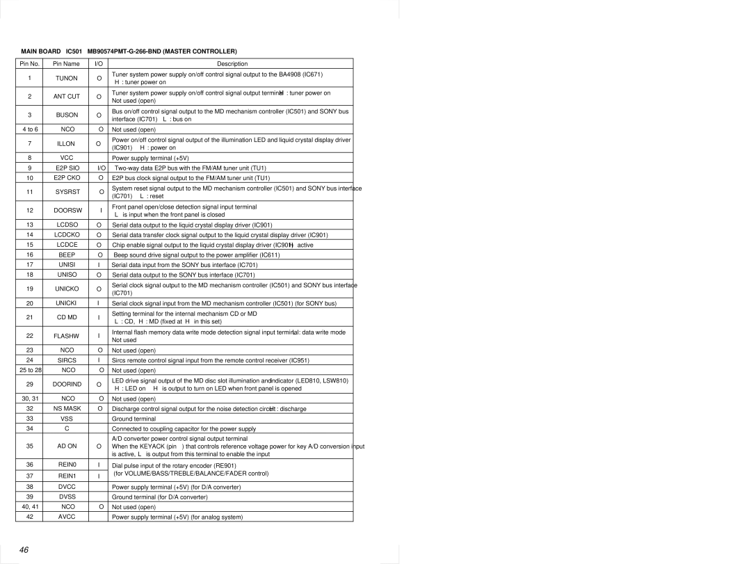
MDX-C6500R, MDX-C6500RX specifications
The Sony MDX-C6500R and MDX-C6500RX are distinguished models in the realm of automotive audio systems, known for their innovative features and superior sound quality. Designed to enhance the driving experience, these units combine functionality with state-of-the-art technology, making them popular choices among car audio enthusiasts.One of the standout features of the MDX-C6500R and MDX-C6500RX is their impressive sound output. Both models are equipped with a high-quality amplifier that delivers clear and powerful audio performance. The incorporation of advanced equalization options allows users to fine-tune the sound to their specific preferences, ensuring an optimal listening experience no matter the genre of music.
The connectivity options are another highlight of these models. The MDX-C6500R and MDX-C6500RX come with built-in CD players, enabling users to enjoy their favorite albums while on the road. Additionally, these units support a variety of audio formats, ensuring compatibility with a wide range of media. For those who prefer digital music, the inclusion of USB ports and auxiliary inputs allows for seamless integration of smartphones and other devices, making it easy to access personal playlists or streaming services.
User interface and functionality have not been overlooked in these models. Both the MDX-C6500R and MDX-C6500RX feature an intuitive control panel with a clear display, allowing for easy navigation through tracks and settings. The rotary volume control provides a tactile experience that enhances usability, while preset functions enable users to save their favorite stations for one-touch access.
In terms of design, both models boast a sleek and modern aesthetic that fits well with the interior of various vehicle types. They are built to withstand the rigors of daily use while maintaining a refined look, making them suitable for both casual listeners and audiophiles alike.
Moreover, these models prioritize safety and convenience. They are designed with features that minimize distractions, ensuring drivers can focus on the road while still enjoying high-quality audio. Some models may also include compatibility with steering wheel controls, further enhancing the user experience.
In summation, the Sony MDX-C6500R and MDX-C6500RX stand out as reliable and feature-rich car audio solutions. With high-quality sound performance, extensive connectivity options, and user-friendly controls, they are ideal for anyone looking to elevate their in-car audio experience. As drivers continue to seek better sound systems, these Sony models remain relevant and desirable choices.

