MDX-CA680/CA680X

TABLE OF CONTENTS


1. GENERAL


Location of Controls

3

Setting the Clock

4

2.DISASSEMBLY

2-1.

Disassembly Flow

10

2-2.

Sub Panel Assy

10

2-3.

Mechanism Deck (MG-164MA-138)

11

2-4.

MAIN Board

11

2-5.

Heat Sink

12

2-6.

SERVO Board

12

2-7.

MD Cover Assy

13

2-8.

Float Block

13

2-9. Lo Motor Assy (Loading) (M903)

14

2-10. Lever (LE23) Assy

14

2-11. Holder Assy

15

2-12. Chucking Arm Assy

15

2-13.

Optical Pick-up (KMS-241C)

16

2-14. SL Motor Assy (Sled) (M902),


SP Motor Assy (Spindle) (M901)

16

3.ELECTRICAL ADJUSTMENTS


Test Mode

17


MD Section

17


Tuner Section

17

4.

DIAGRAMS

18

4-1.

Block Diagram – SERVO Section

23

4-2.

Block Diagram – TUNER Section

24

4-3.

Block Diagram – MAIN Section

25

4-4. Block Diagram – BUS CONTROL/


POWER SUPPLY Section

26

4-5. Note for Printed Wiring Boards and


Schematic Diagrams

27

4-6. Printed Wiring Boards – SERVO Section

29

4-7. Schematic Diagram – SERVO Section (1/2)

30

4-8. Schematic Diagram – SERVO Section (2/2)

31

4-9. Printed Wiring Board – MAIN Board

32

4-10.

Schematic Diagram – MAIN Board (1/3)

33

4-11.

Schematic Diagram – MAIN Board (2/3)

34

4-12.

Schematic Diagram – MAIN Board (3/3)

35

4-13.

Printed Wiring Board – SUB Board

36

4-14.

Schematic Diagram – SUB Board

37

4-15.

Printed Wiring Board – KEY Board

38

4-16.

Schematic Diagram – KEY Board

39

4-17. IC Pin Function Description

41

5.EXPLODED VIEWS

5-1.

General Section

49

5-2.

Front Panel Section

50

5-3. Mechanism Deck Section-1 (MG-164MA-138)

51

5-4.

Mechanism Deck Section-2 (MG-164MA-138)

52

6.

ELECTRICAL PARTS LIST

53

NOTES ON HANDLING THE OPTICAL PICK-UP BLOCK OR BASE UNIT

The laser diode in the optical pick-up block may suffer electro- static break-down because of the potential difference generated by the charged electrostatic load, etc. on clothing and the human body.

During repair, pay attention to electrostatic break-down and also use the procedure in the printed matter which is included in the repair parts.

The flexible board is easily damaged and should be handled with care.

NOTES ON LASER DIODE EMISSION CHECK

Never look into the laser diode emission from right avove when checking it for adustment. It is feared that you will lose your sight.

NOTES ON HANDLING THE OPTICAL PICK-UP BLOCK (KMS-241C).

The laser diode in the optical pick-up block may suffer electro- static break-down easily. When handling it, perform soldering bridge to the laser-tap on the flexible board. Also perform mea- sures against electrostatic break-down sufficiently before the op- eration. The flexible board is easily damaged and should be handled with care.

laser-tap

OPTICAL PICK-UP FLEXIBLE BOARD

Notes on chip component replacement

Never reuse a disconnected chip component.

Notice that the minus side of a tantalum capacitor may be dam- aged by heat.

Flexible Circuit Board Repairing

Keep the temperature of the soldering iron around 270 ˚C dur- ing repairing.

Do not touch the soldering iron on the same conductor of the circuit board (within 3 times).

Be careful not to apply force on the conductor when soldering or unsoldering.

CAUTION

Use of controls or adjustments or performance of procedures other than those specified herein may result in hazardous ra- diation exposure.

SAFETY-RELATED COMPONENT WARNING!!

COMPONENTS IDENTIFIED BY MARK 0 OR DOTTED LINE WITH MARK 0 ON THE SCHEMATIC DIAGRAMS

AND IN THE PARTS LIST ARE CRITICAL TO SAFE OPERATION. REPLACE THESE COMPONENTS WITH SONY PARTS WHOSE PART NUMBERS APPEAR AS SHOWN IN THIS MANUAL OR IN SUPPLEMENTS PUB- LISHED BY SONY.

2

Page 2
Image 2
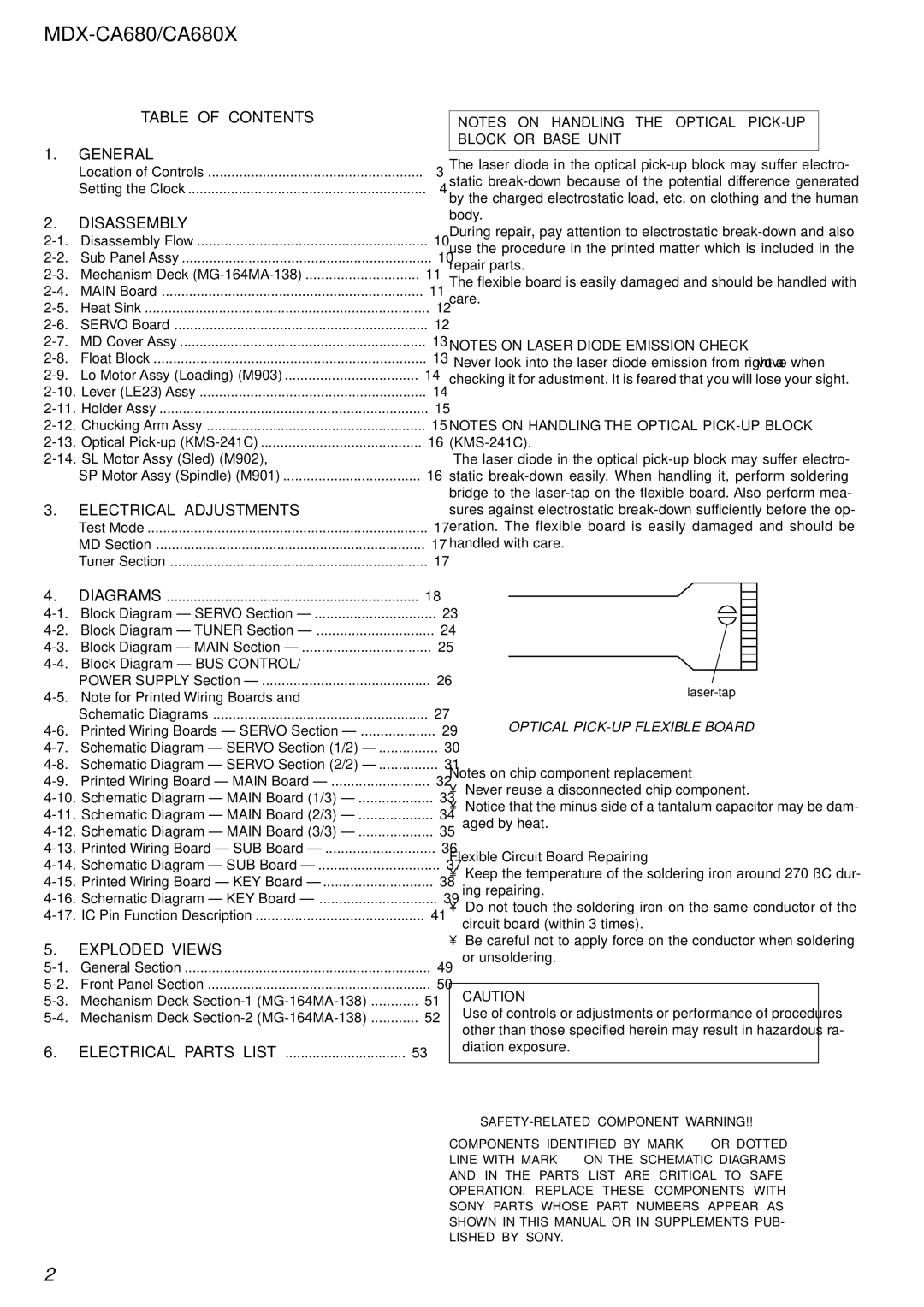
Sony MDX-CA680 service manual Table of Contents General, Disassembly, Electrical Adjustments, Exploded Views

MDX-CA680 specifications

The Sony MDX-CA680 is an advanced multi-disc car audio system that exemplifies Sony's commitment to delivering high-quality sound and innovative features. With its sleek design and user-friendly interface, it stands as a popular choice for audiophiles and casual listeners alike. This model supports both MD (MiniDisc) playback as well as traditional CD formats, providing exceptional versatility for music enthusiasts who prefer various media.

One of the standout features of the MDX-CA680 is its 40 watts maximum output per channel. This power allows for dynamic sound reproduction across a wide range of musical genres. By utilizing Sony's proprietary Dynamic Bass Enhancement technology, the system enriches low-frequency sounds, making them feel fuller and more immersive, perfect for bass-heavy tracks.

The MDX-CA680 is designed with user convenience in mind. Its rotary control knob and intuitive button layout facilitate easy navigation through tracks and settings, allowing drivers to focus on the road while effortlessly managing their audio experience. The system also boasts a detachable faceplate, a crucial security feature for preventing theft.

Another notable characteristic of the MDX-CA680 is its support for various audio formats. Besides MD and CD, the system can handle MP3s, enabling users to create and playback custom playlists with ease. The player’s compatibility with CD-R and CD-RW media also enhances its functionality, allowing users to enjoy burned discs filled with their favorite tunes.

The display on the MDX-CA680 is characterized by a clear and bright LCD screen that provides essential information at a glance. This includes track titles, elapsed time, and artist names, making it easy to follow along with your music. Additionally, the unit supports adjustable EQ settings, allowing users to personalize their audio experience to suit their preferences.

In terms of installation, the MDX-CA680 is designed to integrate seamlessly into various vehicle models, featuring a standard DIN size that fits most aftermarket dashboards. Overall, the Sony MDX-CA680 stands out in the realm of car audio systems, offering a blend of versatility, quality, and user-friendly features that enhance the driving experience, making every journey more enjoyable.