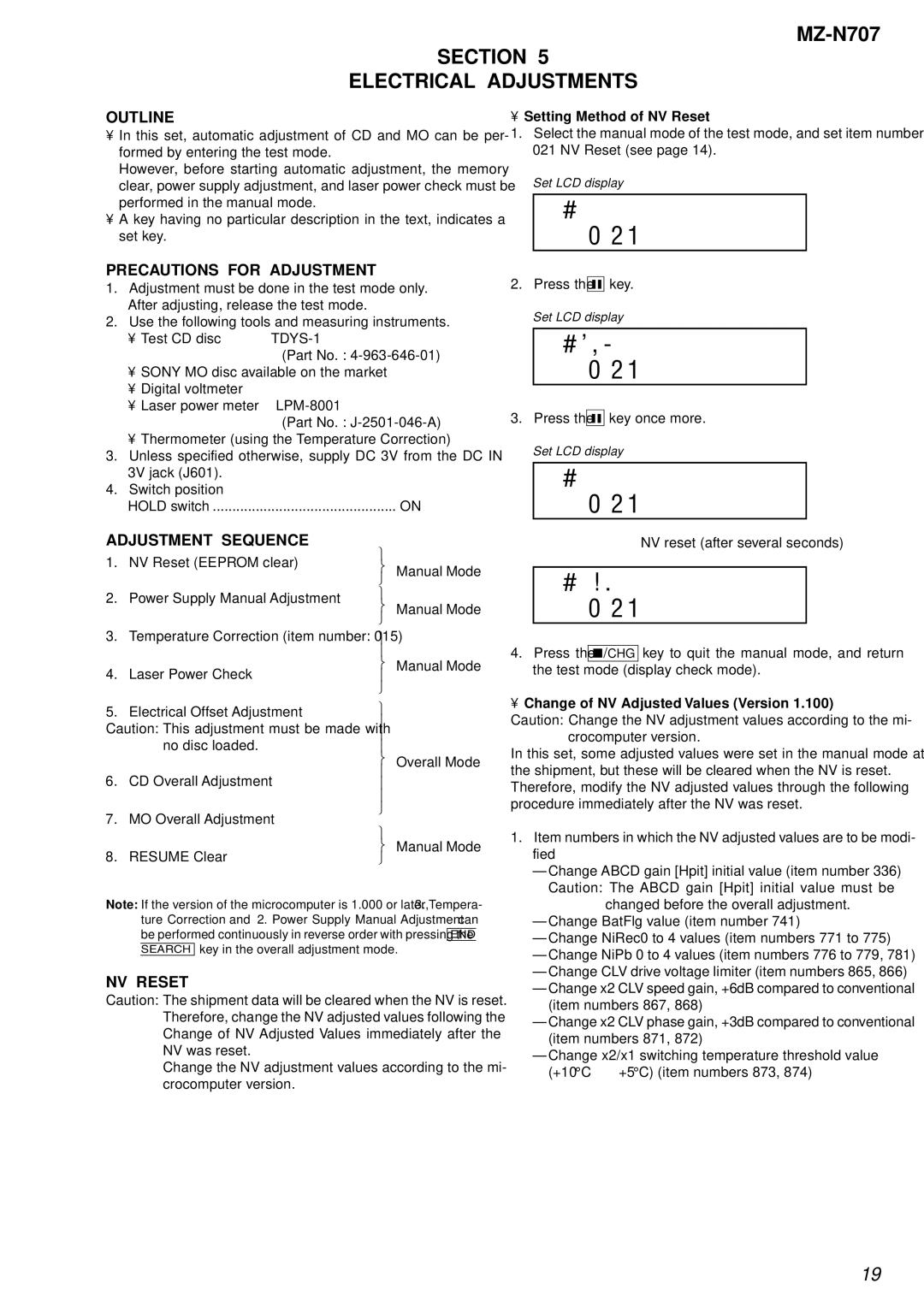
MZ-N707 specifications
The Sony MZ-N707, released in the early 2000s, is a remarkable portable MiniDisc player that represents a significant leap forward in digital audio technology. Known for its compact size and impressive sound quality, the MZ-N707 quickly became a favorite among music enthusiasts during its heyday.One of the standout features of the MZ-N707 is its advanced ATRAC (Adaptive Transform Acoustic Coding) audio compression technology. This proprietary format allows for high-quality audio playback while minimizing file size, making it easier for users to store and carry their favorite tracks. The MiniDisc format supports a variety of bit rates, enabling listeners to choose between higher quality or more storage capacity based on their personal preferences.
The MZ-N707’s sleek and lightweight design is ideal for on-the-go listening, fitting comfortably in a pocket or bag. It boasts a clear LCD display that provides essential information such as track titles, playback time, and battery life, ensuring users stay informed while enjoying their music.
Battery life is another major selling point for the MZ-N707. With the ability to run for several hours on a single charge, this player is perfect for long journeys or extended listening sessions. Additionally, it uses a rechargeable lithium-ion battery, which was a welcome feature at the time, reducing the need for frequent battery replacements and promoting environmental sustainability.
Connectivity options also make the MZ-N707 an appealing choice. It comes with an integrated USB port for easy data transfer between the player and a computer, allowing users to upload their favorite audio tracks with minimal hassle. Furthermore, it supports various audio formats, enabling compatibility with a wide range of music sources.
The MZ-N707 is equipped with a range of customizable sound settings, including equalizer presets that allow users to tailor the audio output to fit their listening preferences. This flexibility enhances the user experience, making it suitable for different genres and environments.
In summary, the Sony MZ-N707 MiniDisc player features cutting-edge technology, portability, excellent battery life, and user-friendly options that appeal to audiophiles and casual listeners alike. Its legacy is a testament to Sony's commitment to innovation in portable audio solutions during the early 21st century. Whether for casual listening or serious music collection, the MZ-N707 remains a notable device in the history of digital audio.

