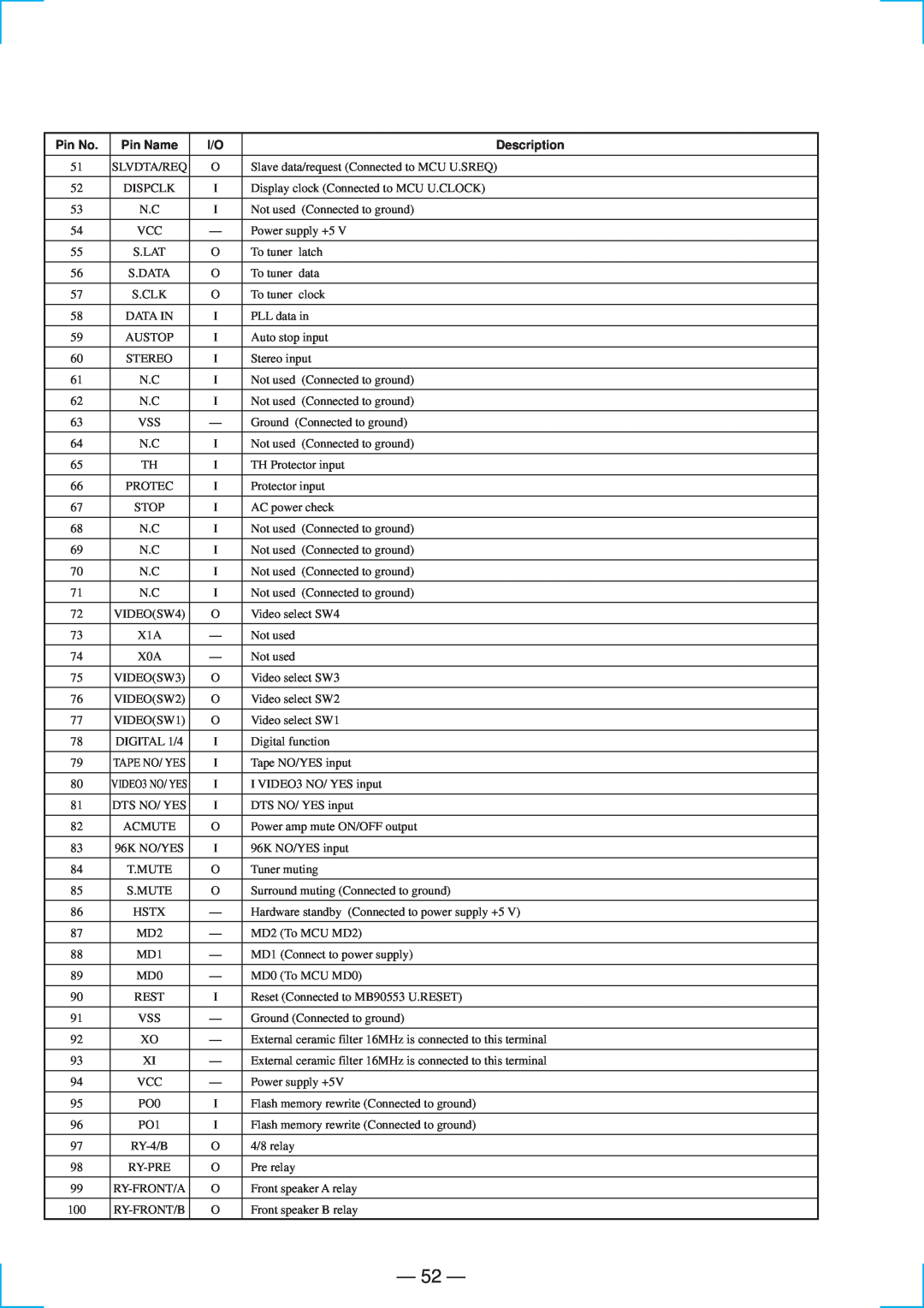
STR-DE835 specifications
The Sony STR-SE951, STR-DE935, and STR-DE835 are classic stereo receivers that showcase Sony's commitment to audio quality, versatility, and innovative technology. Each model reflects Sony's dedication to enhancing the home audio experience, making them popular choices for music enthusiasts and home theater aficionados alike.The Sony STR-SE951 is a high-end receiver that offers a robust power output and an array of features designed to elevate audio performance. It boasts a 100 watts per channel power output, ensuring rich and dynamic sound reproduction. The inclusion of Dolby Pro Logic helps create an immersive surround sound experience, making it suitable for both music and movie playback. The SE951 also features a range of input options, including multiple analog connections, a phono input for turntables, and digital inputs for modern devices, allowing for a versatile setup. Its sleek design and user-friendly layout make it a stylish addition to any audio system.
The STR-DE935 is another remarkable model that emphasizes both performance and ease of use. With 100 watts per channel and advanced sound processing capabilities, the DE935 delivers clear and powerful audio. It supports Dolby Digital and DTS decoding, which enhances the surround sound experience when watching movies. The receiver is equipped with a 5.1-channel output, allowing users to connect a full surround sound system. Its built-in tuner offers access to AM/FM stations, and the inclusion of a user-friendly remote control makes it easy to navigate through settings and sources. The DE935 also features pre-outs for additional amplification, providing flexibility for audiophiles who wish to customize their setups.
The STR-DE835, while slightly more affordable, still embodies Sony's reputation for quality audio. This model provides a solid 80 watts per channel and includes essential features such as a built-in FM/AM tuner, multiple input options, and support for Dolby Surround. Its compact design and straightforward controls make the DE835 an excellent choice for those looking to enhance their home audio without overwhelming complexity. The receiver is designed to deliver clean sound reproduction across its range, making it ideal for both music and everyday media consumption.
All three models reflect Sony's attention to detail in engineering and design, ensuring durability and performance. With their range of features and technologies, the STR-SE951, STR-DE935, and STR-DE835 remain relevant choices for those seeking quality audio solutions, delivering an engaging listening experience for both casual listeners and dedicated audiophiles.

