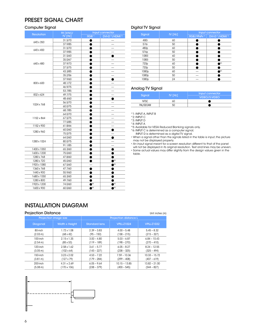
PRESET SIGNAL CHART
Computer Signal
Resolution | fH [kHz]/ | Input connector | ||
fV [Hz] | RGB*1 |
| ||
| ||||
640 x 350 | 31.5/70 |
| — | |
37.9/85 |
| — | ||
|
| |||
640 x 400 | 31.5/70 |
| — | |
37.9/85 |
| — | ||
|
| |||
| 31.5/60 |
|
| |
| 35.0/67 |
| — | |
640 x 480 | 37.9/73 |
| — | |
| 37.5/75 |
| — | |
| 43.3/85 |
| — | |
| 35.2/56 |
| — | |
| 37.9/60 |
|
| |
800 x 600 | 48.1/72 |
| — | |
| 46.9/75 |
| — | |
| 53.7/85 |
| — | |
832 x 624 | 49.7/75 |
| — | |
| 48.4/60 |
|
| |
1024 x 768 | 56.5/70 |
| — | |
60.0/75 |
| — | ||
|
| |||
| 68.7/85 |
| — | |
| 64.0/70 |
| — | |
1152 × 864 | 67.5/75 |
| — | |
| 77.5/85 |
| — | |
1152 x 900 | 61.8/66 |
| — | |
1280 x 960 | 60.0/60 |
|
| |
75.0/75 |
| — | ||
|
| |||
| 64.0/60 |
|
| |
1280 x 1024 | 80.0/75 |
| — | |
| 91.1/85 |
| — | |
1400 x 1050 | 65.3/60 |
|
| |
1600 x 1200 | 75.0/60 |
|
| |
1280 x 768 | 47.8/60 |
|
| |
1280 x 720 | 45.0/60 |
| *6 | |
1920 x 1080 | 67.5/60 | — | *6 | |
1360 x 768 | 47.7/60 |
|
| |
1440 x 900 | 55.9/60 |
|
| |
1680 x 1050 | 65.3/60 |
|
| |
1280 x 800 | 49.7/60 |
|
| |
1920 x 1200 | 74.0/60 | *5 | *5 | |
1600 x 900 | 60.0/60 | *5 | *5 | |
Digital TV Signal
Signal | fV [Hz] | Input connector | ||
RGB/YPBPR*4 | ||||
|
| |||
480i | 60 |
|
| |
576i | 50 |
|
| |
480p | 60 |
|
| |
576p | 50 |
|
| |
1080i | 60 |
|
| |
1080i | 50 |
|
| |
720p | 60 |
| *6 | |
720p | 50 |
|
| |
1080p | 60 | — | *6 | |
1080p | 50 | — |
| |
1080p | 24 | — |
| |
Analog TV Signal
Signal | fV [Hz] | Input connector | |
VIDEO/S VIDEO | |||
|
| ||
NTSC |
|
| |
60 |
| ||
PAL/SECAM | 50 |
|
*1: INPUT A, INPUT B
*2: INPUT C
*3: INPUT D
*4: INPUT A
*5: Available for VESA Reduced Blanking signals only.
*6: INPUT C is determined as a computer signal; INPUT D is determined as a digital TV signal.
•When a signal other than the signals listed in the table is input, the picture may not be displayed properly.
•An input signal meant for a screen resolution different to that of the panel will not be displayed in its original resolution. Text and lines may be uneven.
•Some actual values may differ slightly from the design values given in the table.
INSTALLATION DIAGRAM
Projection Distance |
|
|
|
|
|
|
| Unit: inches (m) | |||
Projection image size |
|
|
|
| Projection distance L |
|
|
| |||
Diagonal |
| Width x Height |
| Standard lens |
|
|
| ||||
| 1.72 x 1.08 |
| 2.39 | – 3.83 |
| 4.00 | – 5.48 |
| 5.45 | – 8.32 | |
|
|
|
| ||||||||
(2.03 m) |
| (68 x 42) |
| (95 – 150) |
| (158 | – 215) |
| (215 | – 327) | |
|
|
|
|
|
|
|
|
|
|
| |
| 2.15 x 1.35 |
| 3.00 | – 4.80 |
| 5.03 | – 6.87 |
| 6.84 – 10.43 | ||
(2.54 m) |
| (85 x 53) |
| (119 | – 189) |
| (198 | – 270) |
| (270 | – 410) |
|
|
|
|
|
|
|
|
|
|
| |
| 2.58 x 1.62 |
| 3.61 | – 5.77 |
| 6.05 | – 8.27 |
| 8.24 – 12.55 | ||
(3.05 m) |
| (102 x 64) |
| (143 | – 227) |
| (238 | – 325) |
| (325 | – 494) |
|
|
|
|
|
|
|
|
|
|
| |
| 3.23 x 2.02 |
| 4.53 | – 7.22 |
| 7.59 – 10.36 |
| 10.33 | – 15.72 | ||
(3.81 m) |
| (127 x 79) |
| (179 | – 284) |
| (299 | – 408) |
| (407 | – 619) |
|
|
|
|
|
|
|
|
|
|
|
|
| 4.31 × 2.69 |
| 6.05 | – 9.64 |
| 10.15 | – 13.85 |
| 13.82 | – 21.00 | |
(5.08 m) |
| (170 × 106) |
| (238 | – 379) |
| (400 | – 545) |
| (544 | – 827) |
|
|
|
|
|
|
|
|
|
|
|
|
Projection distance L
![]() Front of the lens
Front of the lens
![]() Projected image
Projected image
6