Overview
ConnectionsGenlock
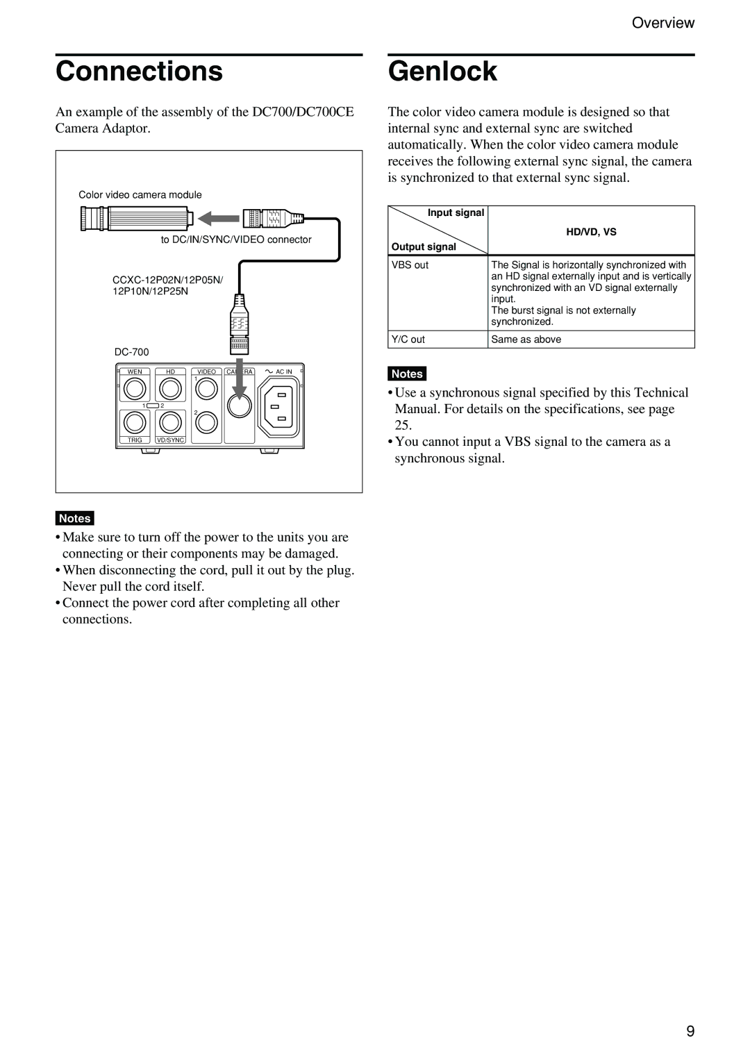
An example of the assembly of the DC700/DC700CE Camera Adaptor.
Color video camera module |
| ||
| to DC/IN/SYNC/VIDEO connector | ||
| |||
12P10N/12P25N |
|
| |
|
|
| |
WEN | HD | VIDEO | AC IN |
|
| 1 |
|
1 | 2 |
|
|
|
| 2 |
|
TRIG | VD/SYNC |
|
|
Notes
•Make sure to turn off the power to the units you are connecting or their components may be damaged.
•When disconnecting the cord, pull it out by the plug. Never pull the cord itself.
•Connect the power cord after completing all other connections.
The color video camera module is designed so that internal sync and external sync are switched automatically. When the color video camera module receives the following external sync signal, the camera is synchronized to that external sync signal.
Input signal |
|
| HD/VD, VS |
Output signal |
|
|
|
VBS out | The Signal is horizontally synchronized with |
| an HD signal externally input and is vertically |
| synchronized with an VD signal externally |
| input. |
| The burst signal is not externally |
| synchronized. |
|
|
Y/C out | Same as above |
|
|
Notes
•Use a synchronous signal specified by this Technical Manual. For details on the specifications, see page 25.
•You cannot input a VBS signal to the camera as a synchronous signal.
9