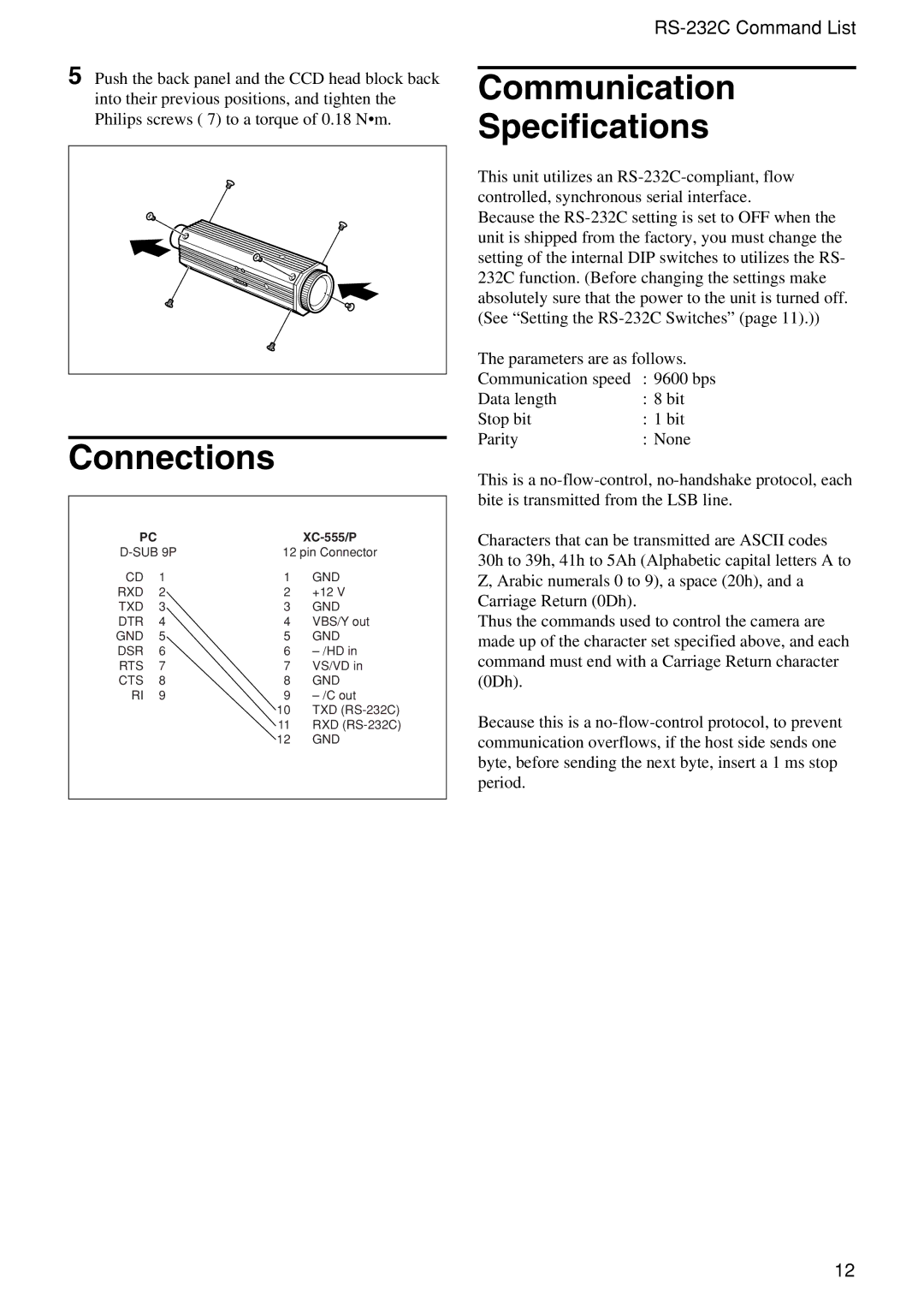
5 Push the back panel and the CCD head block back into their previous positions, and tighten the Philips screws ( 7) to a torque of 0.18 N•m.
Connections
PC |
|
|
|
12 pin Connector | |||
CD | 1 | 1 | GND |
RXD | 2 | 2 | +12 V |
TXD | 3 | 3 | GND |
DTR | 4 | 4 | VBS/Y out |
GND | 5 | 5 | GND |
DSR | 6 | 6 | |
RTS | 7 | 7 | VS/VD in |
CTS | 8 | 8 | GND |
RI | 9 | 9 | |
|
| 10 | TXD |
|
| 11 | RXD |
|
| 12 | GND |
|
|
|
|
Communication
Specifications
This unit utilizes an
Because the
The parameters are as follows.
Communication speed | : 9600 bps | |
Data length | : 8 bit | |
Stop bit | : | 1 bit |
Parity | : | None |
This is a
Characters that can be transmitted are ASCII codes 30h to 39h, 41h to 5Ah (Alphabetic capital letters A to Z, Arabic numerals 0 to 9), a space (20h), and a Carriage Return (0Dh).
Thus the commands used to control the camera are made up of the character set specified above, and each command must end with a Carriage Return character (0Dh).
Because this is a
12
