Pin No. |
| Pin Name | I/O |
|
| Function |
| |||
|
|
|
|
|
|
| ||||
41 |
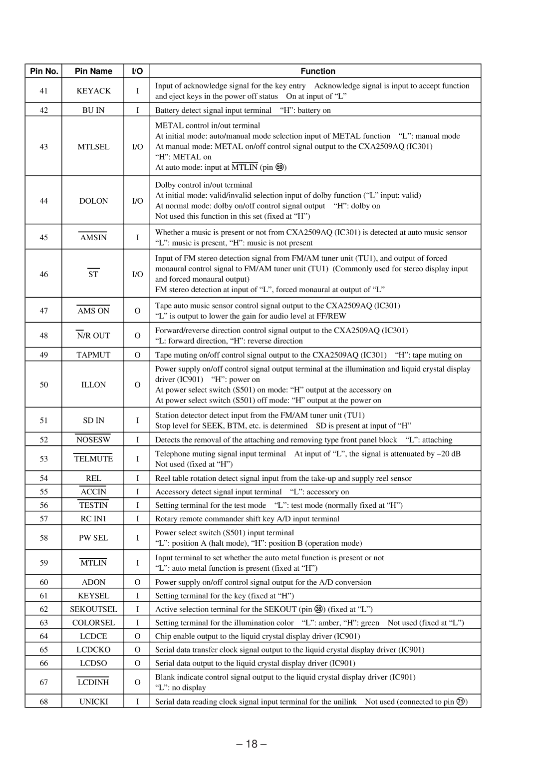
| KEYACK | I | Input of acknowledge signal for the key entry | Acknowledge signal is input to accept function | |||||
| and eject keys in the power off status | On at input of “L” |
| |||||||
|
|
|
|
|
| |||||
|
|
|
|
|
|
|
|
| ||
42 |
| BU IN | I | Battery detect signal input terminal | “H”: battery on |
|
| |||
|
|
|
|
|
|
|
|
|
|
|
|
|
|
|
| METAL control in/out terminal |
|
|
|
|
|
|
|
|
|
| At initial mode: auto/manual mode selection input of METAL function | “L”: manual mode | ||||
43 |
| MTLSEL | I/O | At manual mode: METAL on/off control signal output to the CXA2509AQ (IC301) | ||||||
|
|
|
|
| “H”: METAL on |
|
|
|
|
|
|
|
|
|
| At auto mode: input at MTLIN (pin %») |
|
|
| ||
|
|
|
|
|
|
|
|
|
|
|
|
|
|
|
| Dolby control in/out terminal |
|
|
|
|
|
44 |
| DOLON | I/O | At initial mode: valid/invalid selection input of dolby function (“L” input: valid) | ||||||
| At normal mode: dolby on/off control signal output | “H”: dolby on |
| |||||||
|
|
|
|
|
| |||||
|
|
|
|
| Not used this function in this set (fixed at “H”) |
|
|
| ||
|
|
|
|
|
| |||||
45 |
| AMSIN | I | Whether a music is present or not from CXA2509AQ (IC301) is detected at auto music sensor | ||||||
| “L”: music is present, “H”: music is not present |
|
|
| ||||||
|
|
|
|
|
|
|
| |||
|
|
|
|
|
| |||||
|
|
|
|
| Input of FM stereo detection signal from FM/AM tuner unit (TU1), and output of forced | |||||
46 |
|
| ST | I/O | monaural control signal to FM/AM tuner unit (TU1) | (Commonly used for stereo display input | ||||
|
| and forced monaural output) |
|
|
|
|
| |||
|
|
|
|
|
|
|
|
|
| |
|
|
|
|
| FM stereo detection at input of “L”, forced monaural at output of “L” |
| ||||
|
|
|
|
|
| |||||
47 |
| AMS ON | O | Tape auto music sensor control signal output to the CXA2509AQ (IC301) | ||||||
| “L” is output to lower the gain for audio level at FF/REW |
| ||||||||
|
|
|
|
|
| |||||
|
|
|
|
|
| |||||
48 |
| N/R OUT | O | Forward/reverse direction control signal output to the CXA2509AQ (IC301) | ||||||
| “L: forward direction, “H”: reverse direction |
|
|
| ||||||
|
|
|
|
|
|
|
| |||
|
|
|
|
|
| |||||
49 |
| TAPMUT | O | Tape muting on/off control signal output to the CXA2509AQ (IC301) | “H”: tape muting on | |||||
|
|
|
|
|
| |||||
|
|
|
|
| Power supply on/off control signal output terminal at the illumination and liquid crystal display | |||||
50 |
| ILLON | O | driver (IC901) “H”: power on |
|
|
|
|
| |
| At power select switch (S501) on mode: “H” output at the accessory on |
| ||||||||
|
|
|
|
|
| |||||
|
|
|
|
| At power select switch (S501) off mode: “H” output at the power on |
| ||||
|
|
|
|
|
|
| ||||
51 |
| SD IN | I | Station detector detect input from the FM/AM tuner unit (TU1) |
| |||||
| Stop level for SEEK, BTM, etc. is determined | SD is present at input of “H” | ||||||||
|
|
|
|
| ||||||
|
|
|
|
|
| |||||
52 |
| NOSESW | I | Detects the removal of the attaching and removing type front panel block “L”: attaching | ||||||
|
|
|
|
|
|
| ||||
53 |
| TELMUTE | I | Telephone muting signal input terminal | At input of “L”, the signal is attenuated by | |||||
| Not used (fixed at “H”) |
|
|
|
|
| ||||
|
|
|
|
|
|
|
|
|
| |
|
|
|
|
|
| |||||
54 |
| REL | I | Reel table rotation detect signal input from the | ||||||
|
|
|
|
|
|
|
| |||
55 |
| ACCIN | I | Accessory detect signal input terminal | “L”: accessory on |
| ||||
|
|
|
|
|
|
| ||||
56 |
| TESTIN | I | Setting terminal for the test mode | “L”: test mode (normally fixed at “H”) | |||||
|
|
|
|
|
| |||||
57 |
| RC IN1 | I | Rotary remote commander shift key A/D input terminal |
| |||||
|
|
|
|
|
|
|
|
| ||
58 |
| PW SEL | I | Power select switch (S501) input terminal |
|
|
| |||
| “L”: position A (halt mode), “H”: position B (operation mode) |
| ||||||||
|
|
|
|
|
| |||||
|
|
|
|
|
|
| ||||
59 |
| MTLIN | I | Input terminal to set whether the auto metal function is present or not |
| |||||
| “L”: auto metal function is present (fixed at “H”) |
|
| |||||||
|
|
|
|
|
|
| ||||
|
|
|
|
|
| |||||
60 |
| ADON | O | Power supply on/off control signal output for the A/D conversion |
| |||||
61 |
| KEYSEL | I | Setting terminal for the key (fixed at “H”) |
|
|
| |||
|
|
|
|
|
| |||||
62 |
| SEKOUTSEL | I | Active selection terminal for the SEKOUT (pin #¥) (fixed at “L”) |
| |||||
|
|
|
|
| ||||||
63 |
| COLORSEL | I | Setting terminal for the illumination color “L”: amber, “H”: green Not used (fixed at “L”) | ||||||
|
|
|
|
|
| |||||
64 |
| LCDCE | O | Chip enable output to the liquid crystal display driver (IC901) |
| |||||
|
|
|
|
| ||||||
65 |
| LCDCKO | O | Serial data transfer clock signal output to the liquid crystal display driver (IC901) | ||||||
66 |
| LCDSO | O | Serial data output to the liquid crystal display driver (IC901) |
| |||||
67 |
| LCDINH | O | Blank indicate control signal output to the liquid crystal display driver (IC901) | ||||||
| “L”: no display |
|
|
|
|
| ||||
|
|
|
|
|
|
|
|
|
| |
|
|
|
|
|
| |||||
68 |
| UNICKI | I | Serial data reading clock signal input terminal for the unilink Not used (connected to pin &Á) | ||||||
|
|
|
|
|
|
|
|
|
|
|
– 18 –