NOTE:
•
•Color Indication of Appearance Parts
Example:
KNOB, BALANCE (WHITE) . . . (RED)
− −
Parts Color Cabinet's Color
SECTION 7
EXPLODED VIEWS
•Items marked “*” are not stocked since they are seldom required for routine service. Some delay should be anticipated when ordering these items.
•The mechanical parts with no reference num- ber in the exploded views are not supplied.
•Hardware (# mark) list and accessories and packing materials are given in the last of the electrical parts list.
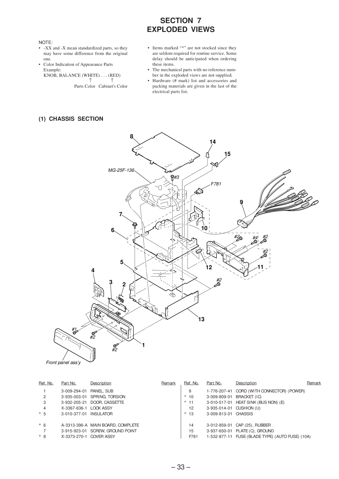
(1) CHASSIS SECTION
8
![]() #3
#3
7
6
5
4
3 2
#1
#2
1
#2
Front panel ass’y
14
15
F781
9
10
#2![]() #4 #2
#4 #2
#2
1211
#2
13
Ref. No. | Part No. | Description | Remark |
1
2
3
4
*5
*6 A-3313-396-A MAIN BOARD, COMPLETE
7
*8
Ref. No. | Part No. | Description | Remark |
9
*10
*11
12
*13
14
15
F781
– 33 –