Connections
Caution
•This unit is designed for negative ground 1°- V DC operation only.
•Be careful not to pinch any wires between a screw and the body of the caz or this u_t or between any moving i_rt_ such as fl_eseat railing, etc.
•Before malting connections, di_onnect the ground terminal of the car battery to avoid short drcuits.
•Connect _e yellow and red power input teaclsonly after all other leads have been connected.
•Be sure to connect the red power input lead to the positive 12 V power terminal which i_ energized
when the tgni_on _ is in the acc_ssozT,it_on.
° Run all ground wires to a common ground point.
•Connect bheye_ow cord to a free car cLrc_t rated higher than the unit'sfuse z_lzng. If you connectthis unit Jn serie_ with other stereo components, the car circuit the" are connected to must be rated higher than the sum of the individua) component'sfu_e rating. If there are no car circuits rated a_ high as the unit'sfuserating, coz_nectthe unit directly to _e battery. If no car c_rcuiteare av_lable for cormecl_ng
this unit, connect the unit to a car cLrcuit rated hi._ er than the u_t'_fuse rating in sLtCha way that if the unit blows its fu_e, no other circuits will be cut off.
Warning when installing in a car without ACC(accessory)position on the ignition key switch
Be sure to press (_ | on the unit for two seconds to torn off the clock display aSter turned off the |
engine. |
|
When you press _ | momentarily, the dock d_spl_y does not turn off and th_s causes batten, wear, |
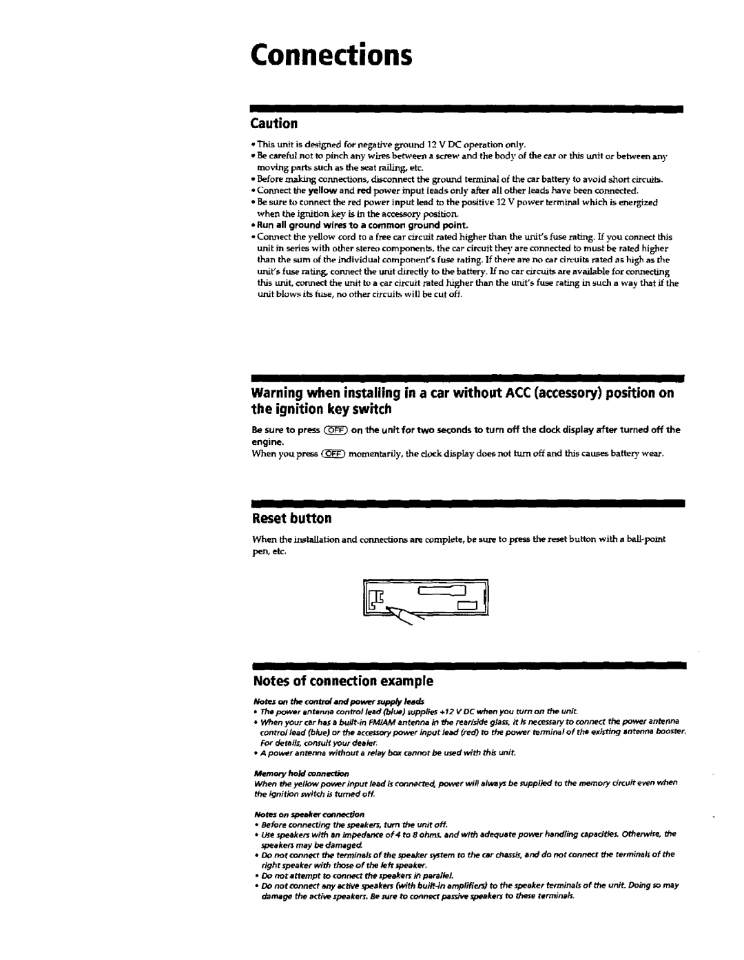
Reset button
When the L_st_[at_on and connections are complete, be sure to p_s the reset button with a
pen, etc.
Notes of connection example
Notes on the €ontm/and povRr supp/y leads
•l_e power antenna control lead (blue) supplies +12 V DC when you turn on the unit.
•When your car has a
•A power antenna Without a relay box cannot be u_ed with th_ uni_
Memo_ hold connection
When the yellow power input lead is €onn_cte_ power wi# always be rupplled to th_ memory circuit even when the ignition switch i_ turned of_
Notes on speaker connecdon
•Before connecting the speaker;, turn the unit off.
•U_e speakers with an impedance of 4 to 8 ohn_. and with adequate power handling ,apecltle_ Otherwise, the speaker may be damagect
•Do not connect 11_ terminals of the _peaker system to the car chassis, and do not connect the terminals of the right speaker with those of the le_ speaker.
•Do not attempt to _onnect the zpeaker_ it_ parallel.
•DO not connect any _tfve speakers (with buitt_n amplifien) to the speaker terminals of the unit. Doing so may damage the active speakers. Be _ure to connect pesdve speakers to these terminals.
