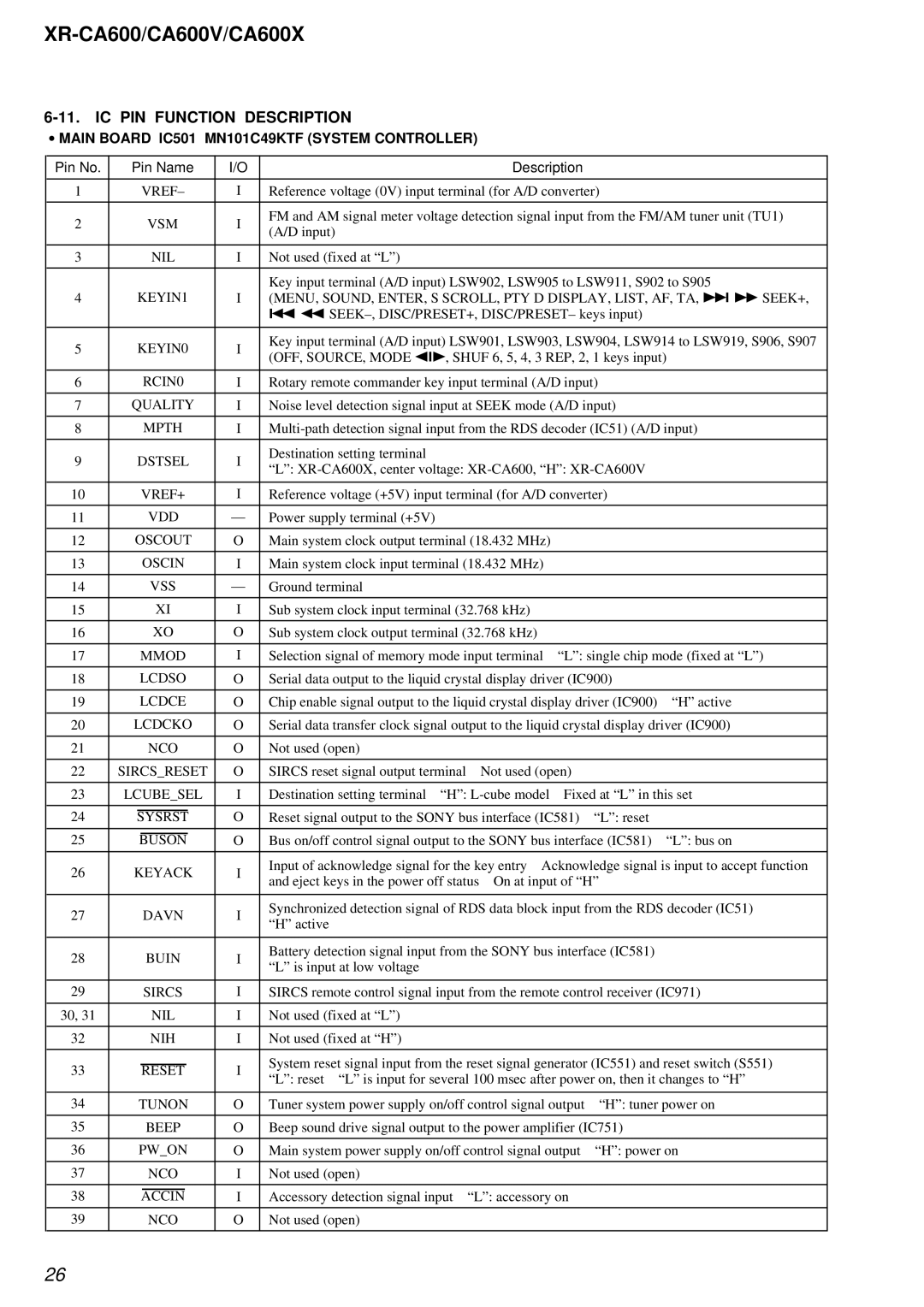
XR-CA600, XR-CA600V, XR-CA600X specifications
The Sony XR-CA600X, XR-CA600V, and XR-CA600 are innovative car audio systems designed for an enhanced in-vehicle listening experience. Each model boasts a blend of modern technologies, impressive features, and user-friendly interfaces, making them popular choices for automotive enthusiasts and casual listeners alike.The XR-CA600X is lauded for its high-quality sound production and user-friendly controls. It features a built-in amplifier with a robust power output, ensuring rich, dynamic sound across all listening levels. With its support for various audio formats, including MP3 and WMA, users can enjoy their favorite tracks with impressive clarity. The device also comes equipped with USB connectivity, allowing users to easily connect their smartphones or USB drives to access their music libraries seamlessly.
On the other hand, the XR-CA600V takes the audio experience a step further with additional visual integration. This model features a vibrant display that not only shows track information but also allows for customization through various visual settings. This can enhance the driving experience, providing a more engaging interface while ensuring safety by minimizing distractions. The XR-CA600V also supports Bluetooth connectivity, facilitating hands-free calling and wireless music streaming, making it a modern solution for staying connected while on the road.
Meanwhile, the XR-CA600 model strikes a balance between functionality and ease of use. It incorporates a straightforward button layout and intuitive interface, making navigation through various settings and functions a breeze. This model does not fall short on sound quality, offering an impressive EQ (equalizer) that allows users to fine-tune their audio preferences to suit different music genres or personal tastes.
All three models boast excellent sound enhancement technologies like digital signal processing and dynamic bass boost, which optimize the audio output for an immersive listening experience. They also feature compatibility with steering wheel controls, providing an added convenience and safety for drivers.
In conclusion, the Sony XR-CA600X, XR-CA600V, and XR-CA600 car audio systems stand out with their impressive combination of sound quality, connectivity options, and user-friendly interfaces. Whether you're looking for a sophisticated audio system with visual features or a straightforward option that delivers on sound performance, Sony's XR-CA600 series provides reliable choices to elevate your in-car audio experience.
