|
| GTR64 |
|
|
|
|
| http://www.matrix.es/GTR64 | ||||
|
|
|
|
|
|
|
|
|
|
|
|
|
|
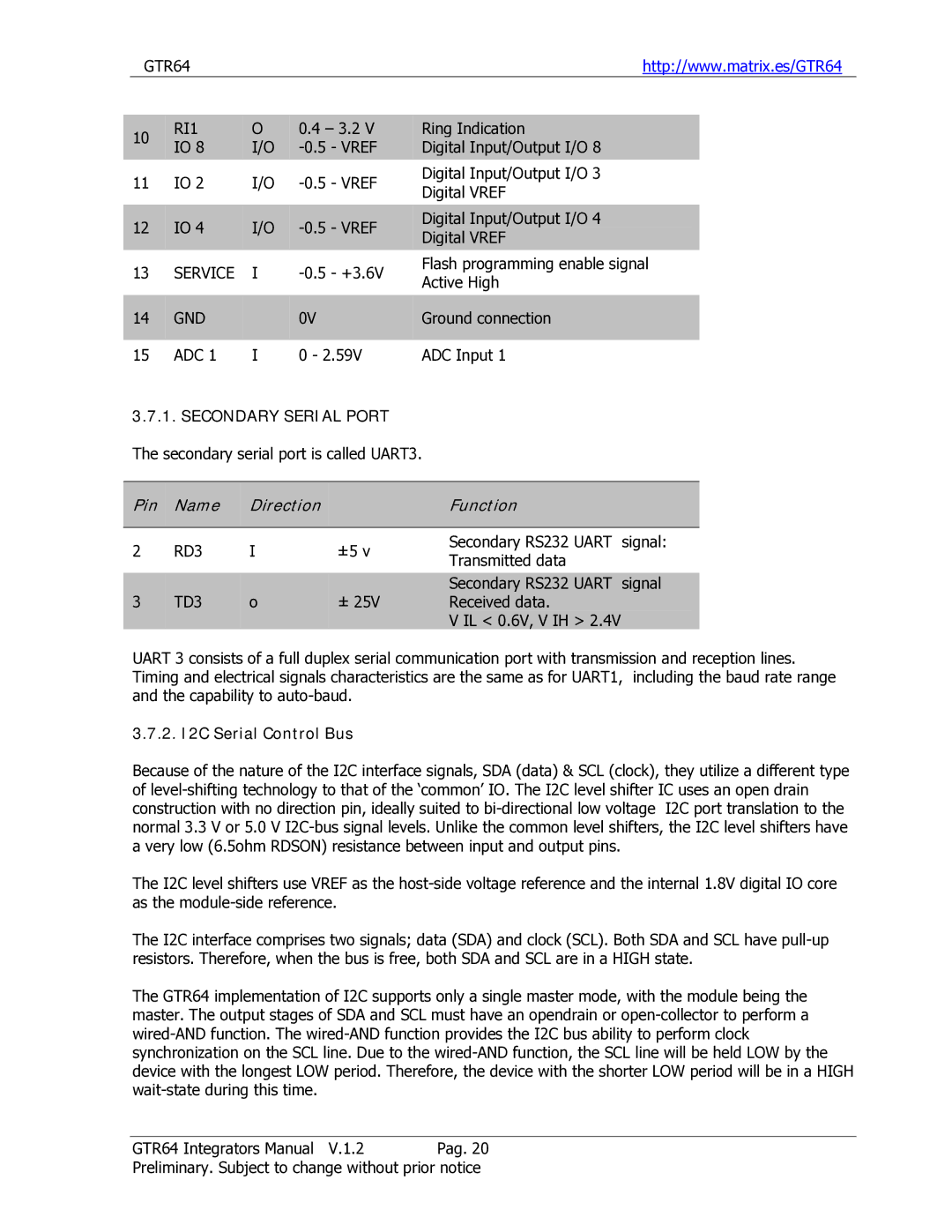
| 10 |
| RI1 |
| O |
| 0.4 – 3.2 V |
| Ring Indication |
|
|
|
|
| IO 8 |
| I/O |
|
| Digital Input/Output I/O 8 |
|
| ||
|
|
|
|
|
|
|
|
| ||||
| 11 |
| IO 2 |
| I/O |
|
| Digital Input/Output I/O 3 | ||||
|
|
|
|
| Digital VREF | |||||||
|
|
|
|
|
|
|
|
|
| |||
|
|
|
|
|
|
|
|
|
|
|
| |
|
| 12 |
| IO 4 |
| I/O |
|
| Digital Input/Output I/O 4 |
|
| |
|
|
|
|
|
| Digital VREF |
|
| ||||
|
|
|
|
|
|
|
|
|
|
|
| |
| 13 |
| SERVICE |
| I |
|
| Flash programming enable signal | ||||
|
|
|
|
| Active High | |||||||
|
|
|
|
|
|
|
|
|
| |||
|
|
|
|
|
|
|
|
|
|
|
| |
|
| 14 |
| GND |
|
|
| 0V |
| Ground connection |
|
|
|
|
|
|
|
|
|
|
|
|
| ||
| 15 |
| ADC 1 |
| I |
| 0 - 2.59V |
| ADC Input 1 | |||
3.7.1. SECONDARY SERIAL PORT
The secondary serial port is called UART3.
| Pin |
| Name | Direction |
|
| Function |
|
|
|
|
|
|
|
|
|
|
| 2 |
| RD3 | I | ±5 v |
| Secondary RS232 UART | signal: |
|
|
| Transmitted data |
| ||||
|
|
|
|
|
|
|
| |
|
|
|
|
|
|
|
|
|
|
|
|
|
|
|
| Secondary RS232 UART | signal |
| 3 |
| TD3 | o | ± 25V |
| Received data. |
|
|
|
|
|
|
|
| V IL < 0.6V, V IH > 2.4V |
|
UART 3 consists of a full duplex serial communication port with transmission and reception lines. Timing and electrical signals characteristics are the same as for UART1, including the baud rate range and the capability to
3.7.2. I2C Serial Control Bus
Because of the nature of the I2C interface signals, SDA (data) & SCL (clock), they utilize a different type of
The I2C level shifters use VREF as the
The I2C interface comprises two signals; data (SDA) and clock (SCL). Both SDA and SCL have
The GTR64 implementation of I2C supports only a single master mode, with the module being the master. The output stages of SDA and SCL must have an opendrain or
GTR64 Integrators Manual V.1.2 Pag. 20
Preliminary. Subject to change without prior notice