GTR64 | http://www.matrix.es/GTR64 |
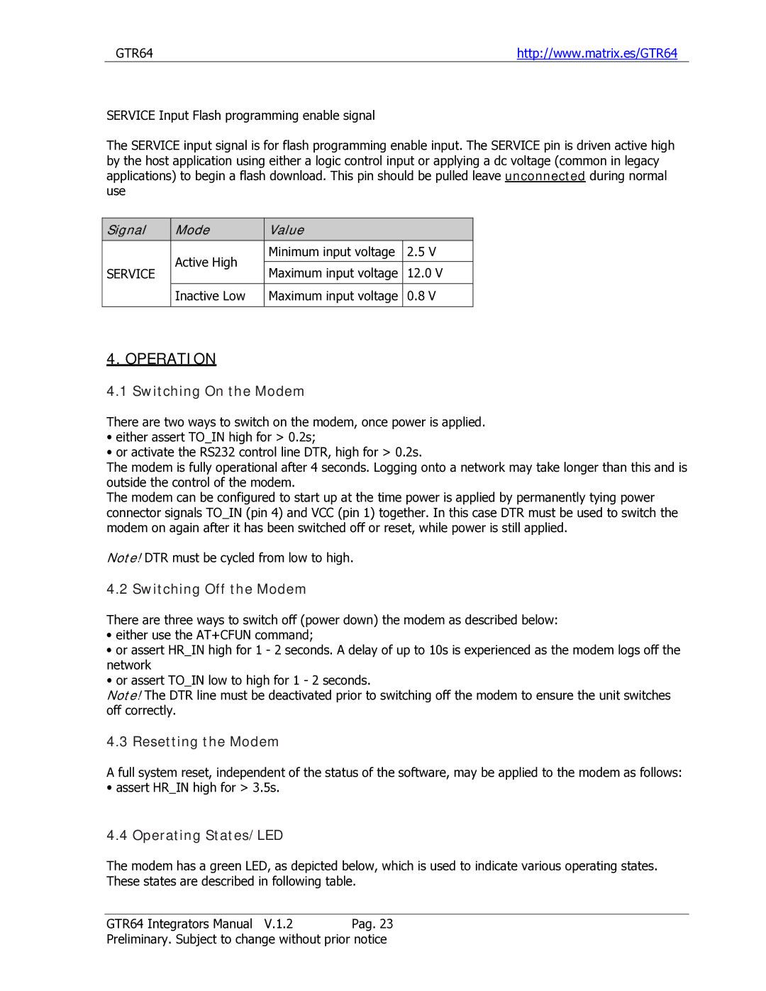
SERVICE Input Flash programming enable signal
The SERVICE input signal is for flash programming enable input. The SERVICE pin is driven active high by the host application using either a logic control input or applying a dc voltage (common in legacy applications) to begin a flash download. This pin should be pulled leave unconnected during normal use
| Signal |
|
| Mode |
|
| Value |
|
|
|
|
|
| Active High |
|
| Minimum input voltage | 2.5 V |
|
|
|
|
|
|
|
|
|
| |
| SERVICE |
|
|
|
| Maximum input voltage | 12.0 V |
| |
|
|
|
|
|
|
| |||
|
|
|
|
|
|
|
|
|
|
|
|
|
| Inactive Low |
|
| Maximum input voltage | 0.8 V |
|
|
|
|
|
|
|
|
|
|
|
4. OPERATION
4.1 Switching On the Modem
There are two ways to switch on the modem, once power is applied.
•either assert TO_IN high for > 0.2s;
•or activate the RS232 control line DTR, high for > 0.2s.
The modem is fully operational after 4 seconds. Logging onto a network may take longer than this and is outside the control of the modem.
The modem can be configured to start up at the time power is applied by permanently tying power connector signals TO_IN (pin 4) and VCC (pin 1) together. In this case DTR must be used to switch the modem on again after it has been switched off or reset, while power is still applied.
Note! DTR must be cycled from low to high.
4.2 Switching Off the Modem
There are three ways to switch off (power down) the modem as described below:
•either use the AT+CFUN command;
•or assert HR_IN high for 1 - 2 seconds. A delay of up to 10s is experienced as the modem logs off the network
•or assert TO_IN low to high for 1 - 2 seconds.
Note! The DTR line must be deactivated prior to switching off the modem to ensure the unit switches off correctly.
4.3 Resetting the Modem
A full system reset, independent of the status of the software, may be applied to the modem as follows:
• assert HR_IN high for > 3.5s.
4.4 Operating States/LED
The modem has a green LED, as depicted below, which is used to indicate various operating states. These states are described in following table.
GTR64 Integrators Manual V.1.2 Pag. 23
Preliminary. Subject to change without prior notice