5. Connection
<RS-232C Connection>
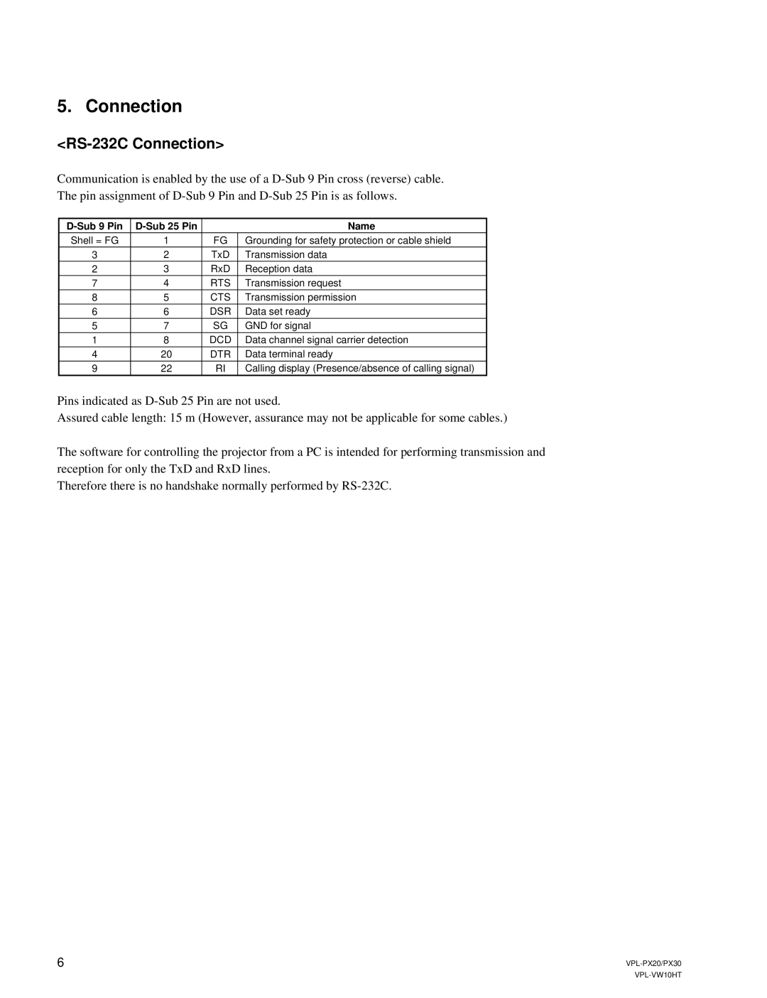
Communication is enabled by the use of a
The pin assignment of
|
|
| Name |
Shell = FG | 1 | FG | Grounding for safety protection or cable shield |
3 | 2 | TxD | Transmission data |
2 | 3 | RxD | Reception data |
7 | 4 | RTS | Transmission request |
8 | 5 | CTS | Transmission permission |
6 | 6 | DSR | Data set ready |
5 | 7 | SG | GND for signal |
1 | 8 | DCD | Data channel signal carrier detection |
4 | 20 | DTR | Data terminal ready |
9 | 22 | RI | Calling display (Presence/absence of calling signal) |
Pins indicated as
Assured cable length: 15 m (However, assurance may not be applicable for some cables.)
The software for controlling the projector from a PC is intended for performing transmission and reception for only the TxD and RxD lines.
Therefore there is no handshake normally performed by
6 |
