4. Data of Code
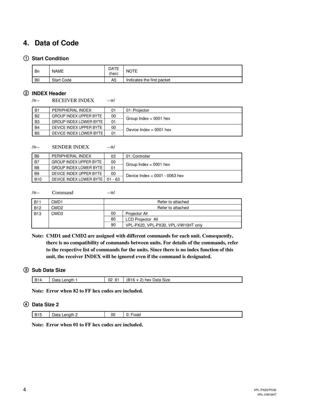
1Start Condition
Bn | NAME | DATE | NOTE | |
(hex) | ||||
|
|
| ||
|
|
|
| |
B0 | Start Code | A5 | Indicates the first packet |
2INDEX Header
RECEIVER INDEX |
| |||
|
|
|
| |
B1 | PERIPHERAL INDEX | 01 | 01: Projector | |
B2 | GROUP INDEX UPPER BYTE | 00 | Group Index = 0001 hex | |
B3 | GROUP INDEX LOWER BYTE | 01 | ||
| ||||
B4 | DEVICE INDEX UPPER BYTE | 00 | Device Index = 0001 hex | |
B5 | DEVICE INDEX LOWER BYTE | 01 | ||
|
SENDER INDEX |
| |||
|
|
|
| |
B6 | PERIPHERAL INDEX | 03 | 01: Controller | |
B7 | GROUP INDEX UPPER BYTE | 00 | Group Index = 0001 hex | |
B8 | GROUP INDEX LOWER BYTE | 01 | ||
| ||||
B9 | DEVICE INDEX UPPER BYTE | 00 | Device Index = 0001 - 0063 hex | |
B10 | DEVICE INDEX LOWER BYTE | 01 - 63 | ||
|
| Command |
| ||
B11 |
| CMD1 |
| Refer to attached |
|
| |||
B12 |
| CMD2 |
| Refer to attached |
B13 |
| CMD3 | 00 | Projector All |
|
|
| 80 | LCD Projector All |
|
|
| 90 |
Note: CMD1 and CMD2 are assigned with different commands for each unit. Consequently, there is no compatibility of commands between units. For details of the commands, refer to the respective list of commands for the units. Since there is no index function of this unit, the receiver INDEX will be ignored even if the command is designated.
3Sub Data Size
B14
Data Length 1
02 81 (B16 +2) hex Data Size
Note: Error when 82 to FF hex codes are included.
4Data Size 2
B15
Data Length 2
00
0: Fixed
Note: Error when 01 to FF hex codes are included.
4 |