Operational Elements


#


E 


° 


U


$

V


'


.


-


' °


-


L


L


#


PP


T


U


#


E


-


'


°.)

'


'


U°E


.


L


#


L


$V


L


L


L


L


L


L


L


L


L


L


°.

)


U


'


.


'


PPT

E#


-


#


L

L


L


L


L


L


L


L


LF-LMF Cut and LF Boost

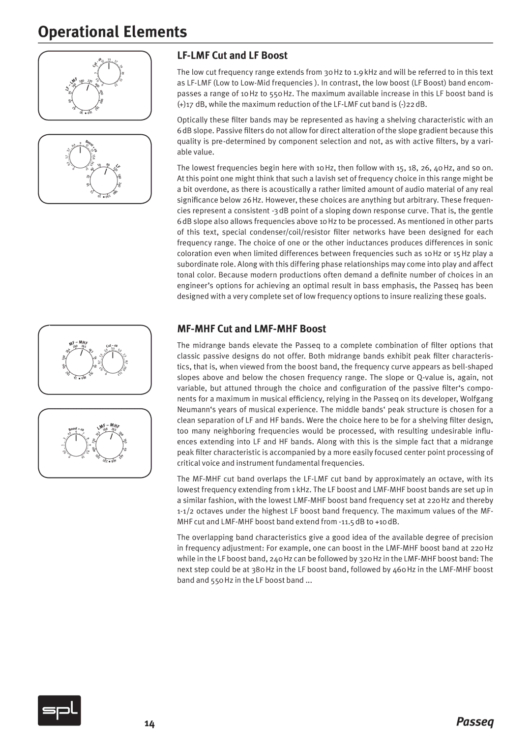
The low cut frequency range extends from 30 Hz to 1.9 kHz and will be referred­ to in this text as LF-LMF (Low to Low-Mid frequencies ). In contrast,­ the low boost (LF Boost) band encom­­ passes a range of 10 Hz to 550 Hz. The maximum available increase­ in this LF boost band is (+)17  dB, while the maximum reduction­ of the LF-LMF cut band is (-)22 dB.

Optically these filter bands may be represented as having a shelving characteristic with an 6 dB slope. Passive filters do not allow for direct alteration of the slope gradient because this quality is pre-determined by component selection and not, as with active filters, by a vari- able value.

The lowest frequencies begin here with 10 Hz, then follow with 15, 18, 26, 40 Hz, and so on. At this point one might think that such a lavish set of frequency choice in this range might be a bit overdone, as there is acoustically a rather limited amount of audio material of any real significance below 26 Hz. However, these choices are anything but arbitrary. These frequen- cies represent a consistent -3 dB point of a sloping down response curve. That is, the gentle 6 dB slope also allows frequencies above 10 Hz to be processed. As mentioned in other parts of this text, special condenser/coil/resistor filter networks have been designed for each frequency range. The choice of one or the other inductances produces differences in sonic coloration even when limited differences between frequencies such as 10 Hz or 15 Hz play a subordinate role. Along with this differing phase relationships may come into play and affect tonal color. Because modern productions often demand a definite number of choices in an engineer’s options for achieving an optimal result in bass emphasis, the Passeq has been designed with a very complete set of low frequency options to insure realizing these goals.

MF-MHF Cut and LMF-MHF Boost

The midrange bands elevate the Passeq to a complete combination of filter options that classic passive designs do not offer. Both midrange bands exhibit peak filter characteris- tics, that is, when viewed from the boost band, the frequency curve appears as bell-shaped slopes above and below the chosen frequency range. The slope or Q-value is, again, not variable, but attuned through the choice and configuration of the passive filter‘s compo- nents for a maximum in musical efficiency, relying in the Passeq on its developer, Wolfgang Neumann‘s years of musical experience. The middle bands‘ peak structure is chosen for a clean separation of LF and HF bands. Were the choice here to be for a shelving filter design, too many neighboring frequencies would be processed, with resulting undesirable influ- ences extending into LF and HF bands. Along with this is the simple fact that a midrange peak filter characteristic is accompanied by a more easily focused center point processing of critical voice and instrument fundamental frequencies.

The MF-MHF cut band overlaps the LF-LMF cut band by approximately an octave, with its lowest frequency extending from 1 kHz. The LF boost and LMF-MHF boost bands are set up in a similar fashion, with the lowest LMF-MHF boost band frequency set at 220 Hz and thereby 1-1/2 octaves under the highest LF boost band frequency. The maximum values of the MF- MHF cut and LMF-MHF boost band extend from -11.5 dB to +10 dB.

The overlapping band characteristics give a good idea of the available degree of precision in frequency adjustment: For example, one can boost in the LMF-MHF boost band at 220 Hz while in the LF boost band, 240 Hz can be followed by 320 Hz in the LMF-MHF boost band: The next step could be at 380 Hz in the LF boost band, followed by 460 Hz in the LMF-MHF boost band and 550 Hz in the LF boost band ...

14

Passeq

Page 14
Image 14
Sound Performance Lab 2595 manual Operational Elements, LF-LMF Cut and LF Boost, MF-MHF Cut and LMF-MHF Boost

2595 specifications

The Sound Performance Lab 2595 is a cutting-edge audio processor designed to elevate mixing and mastering workflows for both professionals and enthusiasts alike. This device stands out in the competitive landscape of audio equipment, thanks to its blend of innovative technologies, high-quality sound processing, and user-friendly features.

One of the main features of the 2595 is its dual-channel architecture. This allows users to process two audio signals simultaneously, making it an ideal choice for stereo applications. Designed for flexibility, the device can be used for various purposes, including mixing, mastering, and live sound reinforcement. The 2595 boasts an intuitive layout, making it easy to navigate its range of functions and settings, even for those who may be new to audio processing.

The heart of the 2595 lies in its advanced digital signal processing (DSP) capabilities. The device is equipped with high-resolution converters, allowing for pristine audio quality with minimal latency. This ensures that the integrity of the original sound is maintained, which is a crucial aspect for any serious sound engineer or musician. Additionally, the built-in algorithms are designed to enhance the audio signal intelligently, providing users with options for dynamic range control, spectral processing, and various filtering techniques.

Another notable characteristic of the Sound Performance Lab 2595 is its extensive connectivity options. The device includes both analog and digital I/O, making it compatible with a wide range of audio sources and studio environments. This versatility is essential for professionals who often work with various formats and formats, ensuring that the 2595 can seamlessly integrate into any setup.

The user experience is further enhanced by the inclusion of a bright, user-friendly display that provides real-time feedback on processing parameters. This feature allows users to make precise adjustments quickly, facilitating a more efficient workflow. Furthermore, the 2595's robust construction ensures that it is built to withstand the rigors of both studio and live applications, making it a reliable choice for any audio professional.

In conclusion, the Sound Performance Lab 2595 represents a significant advancement in audio processing technology. With its dual-channel processing capability, high-quality DSP, extensive connectivity options, and user-friendly interface, it caters to a wide range of audio applications while maintaining exceptional fidelity and performance. This makes the 2595 a valuable tool for anyone looking to achieve professional-grade sound in their projects.