|
| ORG $100 |
| START | LDX #TEXT |
|
| JSR PDATA1 |
|
| JMP CONTRL |
| TEXT | FCB $0D, $0A |
|
| FCC /HELLO/ |
|
| FCB 4 |
|
| END |
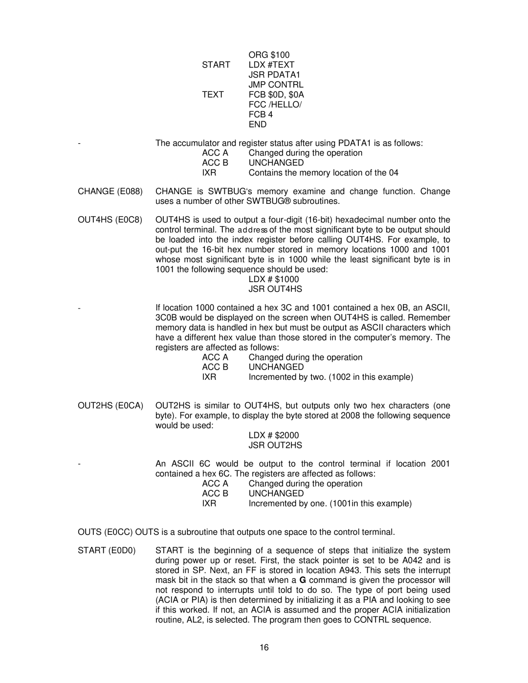
- | The accumulator and register status after using PDATA1 is as follows: | |
| ACC A | Changed during the operation |
| ACC B | UNCHANGED |
| IXR | Contains the memory location of the 04 |
CHANGE (E088) CHANGE is SWTBUG‘s memory examine and change function. Change
| uses a number of other SWTBUG® subroutines. | |
OUT4HS (E0C8) | OUT4HS is used to output a | |
| control terminal. The address of the most significant byte to be output should | |
| be loaded into the index register before calling OUT4HS. For example, to | |
| ||
| whose most significant byte is in 1000 while the least significant byte is in | |
| 1001 the following sequence should be used: | |
|
| LDX # $1000 |
|
| JSR OUT4HS |
- | If location 1000 contained a hex 3C and 1001 contained a hex 0B, an ASCII, | |
| 3C0B would be displayed on the screen when OUT4HS is called. Remember | |
| memory data is handled in hex but must be output as ASCII characters which | |
| have a different hex value than those stored in the computer’s memory. The | |
| registers are affected as follows: | |
| ACC A | Changed during the operation |
| ACC B | UNCHANGED |
| IXR | Incremented by two. (1002 in this example) |
OUT2HS (E0CA) | OUT2HS is similar to OUT4HS, but outputs only two hex characters (one | |
| byte). For example, to display the byte stored at 2008 the following sequence | |
| would be used: | LDX # $2000 |
|
| |
|
| JSR OUT2HS |
- | An ASCII 6C would | be output to the control terminal if location 2001 |
| contained a hex 6C. The registers are affected as follows: | |
| ACC A | Changed during the operation |
| ACC B | UNCHANGED |
| IXR | Incremented by one. (1001in this example) |
OUTS (E0CC) OUTS is a subroutine that outputs one space to the control terminal.
START (E0D0) START is the beginning of a sequence of steps that initialize the system during power up or reset. First, the stack pointer is set to be A042 and is stored in SP. Next, an FF is stored in location A943. This sets the interrupt mask bit in the stack so that when a G command is given the processor will not respond to interrupts until told to do so. The type of port being used (ACIA or PIA) is then determined by initializing it as a PIA and looking to see if this worked. If not, an ACIA is assumed and the proper ACIA initialization routine, AL2, is selected. The program then goes to CONTRL sequence.
16
