Tighten the magnet and transmitter. Do not
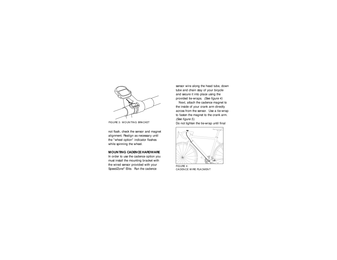
Attach the mount to the handlebar using the bracket screw provided. Tighten so that the bracket cannot rotate on the handlebar. There are sev- eral sizing straps provided to fit differ- ent diameter bars. (See figure 3).
Slide the computer forward onto the mount until it ‘snaps’ into place with an audible click. To remove the computer, push it backward until it releases from the mount. To test for proper installa- tion of the magnet, transmitter and computer, activate the computer by
FIGURE 3: MOUNTING BRACKET
not flash, check the sensor and magnet alignment. Realign as necessary until the "wheel option" indicator flashes while spinning the wheel.
sensor wire along the head tube, down tube and chain stay of your bicycle and secure it into place using the provided
Next, attach the cadence magnet to the inside of your crank arm directly across from the sensor. Use a
Do not tighten the
FIGURE 5: | FIGURE 6: |
CADENCE SENSOR | CADENCE MAGNET |
PLACEMENT | ATTACHMENT |
placement of the magnet is correct. The clearance between the magnet and the sensor should be approximately
pushing the ‘MODE’ (right side) but- ton. Pick up the front of the bicycle and spin the front wheel. The "wheel option" indicator will flash. If it does
MOUNTING CADENCE HARDWARE In order to use the cadence option you must install the mounting bracket with the wired sensor provided with your SpeedZone® Elite. Run the cadence
FIGURE 4:
CADENCE WIRE PLACMENT
4 | 5 |
