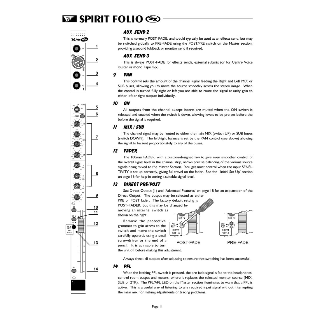
1
2
3
4
5
6
7
8
9
10
11
12
13
14
AUX SEND 2
This is normally
AUX SEND 3
This is always
9PAN
This control sets the amount of the channel signal feeding the Right and Left MIX or SUB buses, allowing you to move the source smoothly across the stereo image. When the control is turned fully right or left you are able to route the signal at unity gain to either left or right outputs individually.
10 ON
All outputs from the channel except inserts are muted when the ON switch is released and enabled when the switch is down, allowing levels to be
11 MIX / SUB
The channel signal may be routed to either the main MIX (switch UP) or SUB buses (switch DOWN). The left/right balance is set by the PAN control (see above) allowing the signal to be sent proportionately to any of the buses.
12 FADER
The 100mm FADER, with a
13 DIRECT PRE/POST
See Direct Output (1) and ‘Advanced Features’ on page 18 for an explanation of the
Direct Output. The output may be selected as either |
| ||
PRE or POST fader. The factory default setting is |
| ||
| |||
moving an internal switch as |
|
| |
shown on the right. |
|
| |
Remove the protective |
|
| |
grommet to gain access to the |
|
| |
switch and move the switch |
|
| |
carefully upwards using a small |
|
| |
screwdriver or the end of a |
|
| |
pencil. It is advisable to turn | |||
|
| ||
the unit off before making this adjustment.
Always check all outputs after adjusting to ensure that switching has been successful.
14 PFL
When the latching PFL switch is pressed, the
Page 11
