Marley / MC Fluid Cooler / Engineering Data : Schematic
9
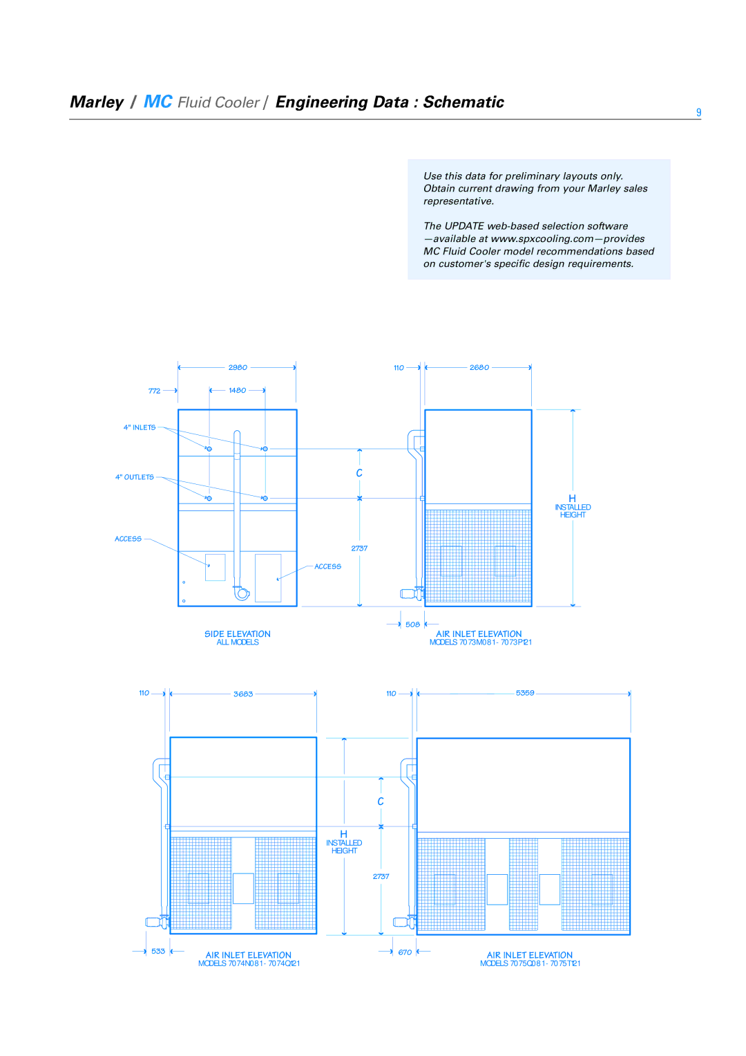
Use this data for preliminary layouts only. Obtain current drawing from your Marley sales representative.
The UPDATE
| 2980 | 110 | 2680 |
772 | 1480 |
|
|
4" INLETS |
|
|
|
4" OUTLETS |
| C |
|
ACCESS |
| 2737 |
|
|
|
| |
|
| ACCESS |
|
|
|
| 508 |
| SIDE ELEVATION |
| AIR INLET ELEVATION |
| ALL MODELS |
| MODELS 7073M081 - 7073P121 |
H
INSTALLED
HEIGHT
110 | 3683 | 110 | 5359 |
|
| C |
|
|
| H |
|
|
| INSTALLED |
|
|
| HEIGHT |
|
|
| 2737 |
|
533 | AIR INLET ELEVATION | 670 | AIR INLET ELEVATION |
| MODELS 7074N081 - 7074Q121 |
| MODELS 7075Q081 - 7075T121 |